ZFS includes some great features that help deliver lightning fast read speeds for storage. Two such features are Adapative Replacement Cache (ARC), and a second possible cache tier, L2ARC. Together these features can dramatically decrease the number of reads required from magnetic storage.
Usually ZFS will assign all but 1GB of system memory to ARC. When files are retrieved they are cached in system RAM dedicated to ARC. This allows them to be retrieved very quickly the next time they are read.
A second tier of cache named L2ARC is also possible. This is where you can dedicate solid state disks to act as another tier of cache. L2ARC only really makes sense when you are fronting slower magnetic spinning disks with cache, and you won’t have enough RAM to support a large enough ARC either. L2ARC doesn’t make a lot of sense if you are already running storage pools across solid state drives.
Another point to consider is that if your requirements mandate a large ARC size, system memory will start to get very expensive. If you are using magnetic storage tiers, then using SSD for L2ARC becomes a much cheaper option than simply dumping piles of money into more memory.
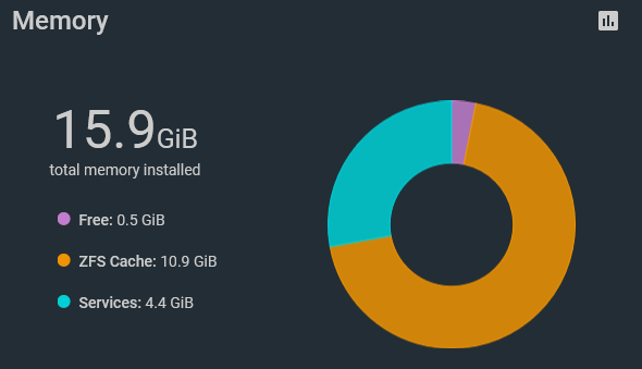
My personal FreeNAS server has 16GB of RAM, with much of that dedicated to ARC.
Analyzing ZFS ARC hit rates for Web Traffic to this Blog
I’ve been running this blog on my personal Kubernetes Raspberry Pi Cluster, which has its storage provisioned via NFS from my FreeNAS storage server.
The storage and cache breakdown is:
4 x 3TB SATA spinning disks, RAIDZ1
2 x 250GB SSD SATA disks, ZFS Mirror
16GB RAM, around 4GB used for jails and VMs, the remaining for ARC
No L2ARC. NFS storage is provided from the SSD based storage pool
This blog has a bunch of static files along with it’s WordPress installation, plus a MySQL database. Both of these sets of files are provisioned from NFS on the ZFS mirror storage pool, utilizing Kubernetes PVs.
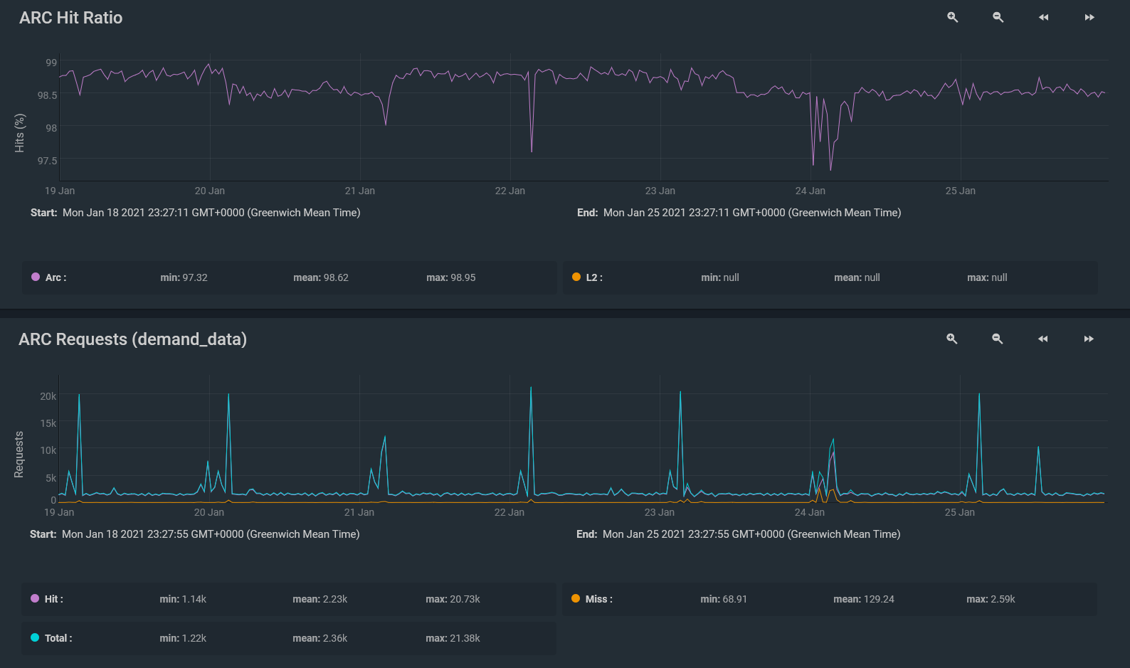
The SSD storage is already quite fast, but the cache features of ZFS really help here when serving frequent random IO generated from web traffic. Just take a look at these two charts:
ARC Hit Ratio and ARC Requests. Notice the really high (almost 100%) ARC hit ratio.
Instead of constantly reading from SSDs and causing unecessary wear, web traffic file requests are mostly served from ARC.
From these two graphs, I can tell that right now 16GB of system memory is perfectly fine for my home storage and web traffic serving needs. ARC is handling these workloads perfectly, with a very high cache hit ratio too.
Secondly, I certainly don’t need L2ARC. Web content is already sitting on SSD storage. Additionally, even if files were on magnetic storage, the main ARC would still be able to serve almost all web traffic.
Conclusion
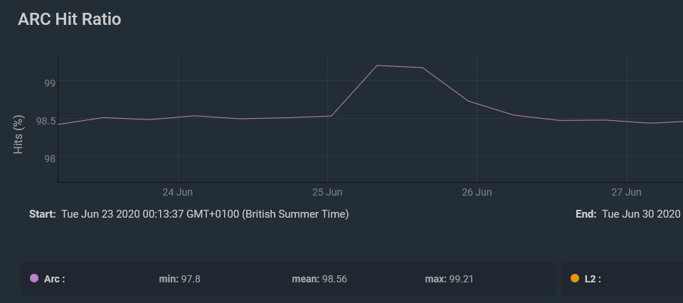
ZFS ARC impresses all around. On it’s busiest day of web traffic last year, this blog saw 12000 sessions, and around 13500 page views in just a few hours. ZFS ARC happily served the site’s storage needs from system memory.
In fact, the ARC hit ratio actually increased to just over 99% at this point in time!
Setting up a new HP P2000 G3 FC MSA with dual controllers over the last couple of days for a small staging environment, I ran into issues from the word go. The device in question was loaded with 24 SFF disks and two Controllers (Controller A and B).
On the very first boot we noticed a fault (amber) LED on the front panel. Inspecting the back of the unit, I noticed that Controller A and B were both still flashing their green “FRU OK” LEDs, (which according to the manual means that the controllers were still booting up), even after waiting a number of hours. On Controller A, I could see a blinking amber “Fault/Service Required” LED. Following through the troubleshooting steps in the manuals lead nowhere as the end synopsis was to check the event logs. Even the Web interface was acting up – I could not see the controller’s listed, could not see any disks and the event logs were completely empty. Obviously there was a larger issue at hand preventing the MSA and even the Web interface from functioning properly. To further confuse matters, after shutting down and restarting the device, controller B starting blinking the amber LED instead of A this time, both still stuck in their “Booting up” state. Refer to the linked LED diagram below and you’ll see that the LED flashing green is labelled as 6, and the amber blinking LED is the one labelled as 7 on the top controller in the diagram.
After powering the unit down completely, and then powering back up again, the MSA was still stuck in the same state. Powering down the unit once more, removing and reseating both controllers did not help either. Lastly, I powered it all off again, removed controller A completely, then powered up the device with just Controller B installed. Surprisingly the MSA booted up perfectly, and LED number 6 (FRU OK) went a nice solid green after a minute or so of booting up. No amber LEDs were to be seen. Good news then! Hot plugging controller A back in at this stage with the device powered on resulted in both controllers reporting a healthy status and all the disks and hardware being detected. A final test was done by powering off everything and powering it back up again as it should be from a cold start. Everything worked this time.
Here is a photo of the rear of the device once all was resolved showing the solid green FRU OK LEDs on both controllers.
Bit of an odd one, but it would seem that controllers together were preventing each other from starting up. Removing one then booting up with this seemed to solve the problem, and at the end of the day all hardware was indeed healthy. After this the 24 disks were assigned and carved up into some vdisks to be presented to our ESXi hosts!
In the last post [Part 1/2], we prepared our VSA, created a management group and cluster in the CMC, and then initialized our disks. Next up, we’ll be creating a Volume which will be presented to our ESXi hosts as an iSCSI LUN. Before we do this though, we need to make sure our hosts can see this LUN. Therefore we’ll be making entries for each of our ESXi hosts using their iSCSI initiator names (IQNs).
Preparing your iSCSI Adapter
If your ESXi hosts don’t already have a dedicated iSCSI adapter you’ll need to use the VMware Software iSCSI adapter. By default this not enabled in ESXi 5.0. This is simple to fix – we just need to get it added. Select your first ESXi host in the Hosts & Clusters view of the vSphere Client, and click Configuration -> Storage Adapters -> Add -> Select “Add Software iSCSI Adapter”. Click OK to confirm.
Now we need to find the IQN of the iSCSI adapter. In the vSphere client, select the iSCSI adapter you are using and select Properties on it under Storage Adapters. This will bring up the iSCSI Initiator Properties. Click the Configure button and copy the iSCSI Name (IQN) to your clipboard.
Getting the iSCSI adapter IQN using the vSphere Client
Quick tip: you can also fetch your iSCSI adapter information (including the IQN) using esxcli. Login to your host using the vMA appliance, the DCUI, or SSH for example and issue the following command, where “vmhba33” is the name of the adapter you want to fetch info on:
esxcli iscsi adapter get -A vmhba33
Getting the iSCSI adapter IQN using ESXCLI
Configuring a Server Cluster and the Server (Host) entries in the CMC
We’ll now create “Servers” in the HP CMC which are what we’ll be adding to our “SAN LUN” later on to allow our ESXi hosts access. In the CMC go to Servers and then click Tasks -> New Server Cluster. Give the Cluster a name and optional description, then click New Server. Enter the details of each ESXi host (Click New Server for each host you have in your specific cluster). For each ESXi host, the Initiator Node Name is the iSCSI Name, or IQN we got from each ESXi host in the step above. The Controlling Server IP Address in each case should be the IP address of your vCenter Server. For this example we won’t be using CHAP authentication, so leave that at “CHAP not required”. Once all your ESXi hosts are added to the new cluster, click OK to finish.
Creating a new Server Cluster and adding each ESXi host and it's corresponding iSCSI Names/IQNs
Creating a new Volume and assigning access to our Hosts
Back in the CMC, with our disks that are now marked as Active we’ll now be able to create a shiny new Volume which is what we will be presenting to our ESXi hosts as an iSCSI LUN. Right-click “Volumes and Snapshots” and then select “Create New Volume”
Enter a Volume Name and Reported Size. You can also use the Advanced Tab to choose Full or Thin provisioning options, as well as Data Protection level (if you had more than one VSA running I believe).
Now we’ll need to assign servers to this Volume (We’ll be assigning our whole “Server Cluster” we created earlier to this Volume to ensure all our ESXi hosts get access to the volumen. Click Assign and Unassign Servers, then tick the box for your Server Cluster you created and ensure the Read/Write permission is selected. Then click OK
Assign the Server Cluster to the Volume for Read/Write access
Final setup and creating our Datastore with the vSphere Client
Go back to the vSphere client, go to one of your ESXi hosts, and bring up the Properties for your iSCSI adapter once again. We’ll now use “Add Send Target Server” under the Dynamic Discovery tab to add the IP address of the P4000 VSA. Click OK then Close once complete.
You should be prompted to Rescan the Host Bus Adapter at this stage. Click Yes and the Rescan will be begin. After the Scan is complete, you should see your new LUN is being presented as we’ll see a new device listed under your iSCSI Adapter (vmhba33 in my case for the Software iSCSI adapter).
New device found on the iSCSI Software adapter
Now that everything is prepared, it is a simple case of creating our VMFS datastore now from this LUN for our ESXi hosts to use for VM storage. Under Hosts & Clusters in the vSphere Client, go to Configuration, then Storage. Click Add Storage near the top right, and follow the wizard through. You should see the new LUN being presented from our VSA, so select that and enter the details of your new Datastore – Capacity, VMFS file system version and Datastore Name. Finish off the wizard and you are now finished. The new datastore is created, partitioned and ready to be accessed!
Add Storage Wizard
Complete - the new datastore is added
Well, that is all there is to it. To summarise, we have now achieved the following over the course of these two blog posts:
Installing and configuring the P4000 LeftHand VSA
Setting up the CMC
Creating a VSA Management Group
Creating a VSA Standard Cluster
Creating Servers entries in a new Server Cluster for each of our ESXi hosts to be presented the storage
Creating a LUN / Storage Volume
Configuring the ESXi hosts to find our VSA in the vSphere Client
Adding the Storage to our ESXi hosts and Creating our VMFS Datastore using the vSphere Client
To conclude, I hope this series has been helpful and that you are well on your way to setting up iSCSI shared storage for your VMware Cluster! As always, if you spot anything that needs adjusting, or have any comments, please feel free to add feedback in the comments section.
I have had a few people asking how I set up my Shared iSCSI storage for my own VMware Lab environment I run at home – the same lab I used to study for my VCP 4 and VCP 5 exams. So, I thought I would write up a blog post detailing how to go about setting this up and trying it out for yourself.
You have NFS shared storeage up and running for your ESXi hosts in your lab, but what about iSCSI? There are many different options out there. Here are a few I can think of off the top of my head:
FreeNAS VM
OpenFiler VM
HP P4000 Lefthand VSA trial
Hardware based – for example Iomega StorCenter IX2 series or QNAP NAS device
The last two options (hardware based are less feasible for a lab environment as you ideally don’t want to pay for something you will be testing. That being said, I was quite keen on the HP P4000 LeftHand VSA, as it offers the same kind of interface that you would use with the actual hardware version as well as some really cool enterprise-like features, such as clustering. In fact, as I understand, many businesses actually use the P4000 VSA in production – it was in the game before VMware came out with their own Virtual shared storage solution. Both of these solutions actually provide highly available shared storage for your ESXi hosts. Anyway, enough of the small talk – lets get on to setting up some shared iSCSI storage for our ESXi hosts to use for running Virtual Machines.
Deciding where to run your P4000 VSA VM
First of all download the trial of the HP P4000 LeftHand VSA. Once you are signed up for the free trial, you should get two options – one version for “Laptops” and one for “ESX”. Grab the relevant version – I chose to run my VSA VMs directly in VMware Workstation 8 and allowed my ESXi VMs access to their storage. If you want to run your VSAs as VMs on your ESXi host VMs then grab the “ESX” version. Once you have it downloaded, extract the download into a convenient location. I wanted my VSA to run on faster disks in my home system, so I moved the extracted files to an SSD volume. Remember to take this into consideration for your lab too – VMs will be running on this, so plan your lab VM deployment and storage carefully. Once ready, simply right-click the VSA.vmx configuration file and select “Open with VMware Workstation”. (Or add to Inventory if you are using the ESX version and browsing the VSA with your Datastore Browser).
Configuration
Now that we have the VSA VM inventoried, we need to create some additional virtual disks for it to use (by default it just has a disk used for it’s OS). Right-click the VM and add some disks. There is one important thing you should note here – the disks should be added on SCSI devices 1:0 and onwards. I added 3 x Virtual Disks to my VSA. Note that a storage total of more than 500GB will require your VSA VM to have more than 768 RAM). I chose 3 x 80GB Virtual disks, meaning I would get a RAID5 160GB volume at the end of this exercise. I found out the hard way (troubleshooting a VSA that would not work) that your VSA needs around 1GB or more of RAM if you have more than 500GB of storage on it! Keep this figure under 500GB and you can get away with the default 384MB RAM which is ideal for a home lab. So here are the details I used for each Virtual Disk added (a total of 3 of these):
New Virtual Disk
SCSI (Recommended)
Mode -> (Independent) -> Persistent
Enter size of disk – for e.g. 80GB
Thin provisioned (Leave “Allocate all disk space now” unticked) – to save disk space on those SSDs especially!
Store Virtual Disk as a Single File
Specify Virtual Disk filename
Important: If you didn’t get an option to specify the Virtual Device Node, go back to “Advanced” on each disk and change to device node x, where x is Virtual Device Node SCSI 1:1 to 1:3. (a different node for each disk you added). If you do not specify these selections, then the VSA will not detect your disks or be able to use them.
Remeber to use these Virtual Device Nodes for each disk added.
Once your disks are added, ensure it is on the right VM network (I used bridged in Workstation for my lab), your network situation will of course vary. Then power up the VSA. Whilst it is powering up, we’ll need to get the HP P4000 Centralized Management Console installed on a “management” PC. In your VSA download you should have also received the installer for this. Simply run the installer and go through the wizard to get this installed.
P4000 Centralized Management Console Installer
Back to your VSA console, you should now be at the login prompt – type Start to login, then press Enter at the “Login” screen. We’ll now be presented with a menu:
Navigate to Network TCP/IP Settings and choose your eth0 adapter. Configure a hostname for your VSA – in my example I used “blogvsa.noobs.local”. Don’t forget to set your VSA up to have a static IP address and enter your network details. If you have a DNS server, now would be a good time to also add an A Name Record for your VSA’s hostname and assign it the IP address you configured it with. Accept the network changes for the VSA and wait for it to apply the new settings.
Hostname and Network configuration.
Now launch your HP P4000 Centralized Management Console from the machine you installed it on, and we’ll begin setting this VSA up. Once open, you should have a few options to the left, and hopefully, the CMC would have already found your new VSA on the network. If not, don’t stress – just use the menu option Find -> Find Systems -> Find. Once the VSA is discovered, you can then close the “Find” window and view the VSA under Available Systems.
Expand Available Systems and locate your newly powered up VSA.
Next, we’ll create a new Management Group and add the VSA to it. The group will exist on this VSA as it is our only storage system. Right click on the VSA and choose Add to New Management Group. Give the group a suitable name, then click Next. The next screen asks us to create an Administrative user. Enter the details for a new admin account and then click Next. Specify NTP server settings, or set the time manually then click Next. Set up your DNS Server and Domain Name on the next screen, then click Next. If you have an SMTP server to use for email alerts, enter those settings on the next screen, or continue. To keep things simple, on the “Create Cluster” page, select the default “Standard Cluster” option, continue, give it a name, then click Next. The next screen requires you to specify a Virtual IP for Fault Tolerance or load-balanced iSCSI access. Add an IP and the correct subnet mask then click Next. The next screen allows us to create a volume. We have not set up our disks and RAID yet, so check the option to “Skip Volume Creation” and we’ll come back to that afterwards. Finish the wizard and wait for it to create the Management Group and configure everything for you. Once complete, it should auto-login to the Management Group using the admin user you specified for you. Review the summary once complete and close the wizard.
Now, expand out your Storage Cluster under the new Management Group and find your VSA system. Select Storage and then click the Disk Setup tab. We’ll now initialize each disk that we added to the VSA earlier and add it to the RAID group for the VSA. Right-click each uninitialized disk and select “Add Disk to RAID“.
Add each uninitialized VSA disk to the RAID group.
This post is getting a little long now, so I’ll end off this post here with our VSA configured, the Management Group and Cluster set up, and our disks initialized. In the next post [part 2/2], we’ll create a new Volume with these disks and will be setting up our iSCSI initiators from our ESXi hosts as “Servers” in the CMC. After this, we will present the new Volume to our ESXi hosts as an iSCSI LUN and create our VMFS shared storage for vSphere to use. Stay tuned, as part 2 will be coming soon! (Hopefully tomorrow!) See below for the next section: