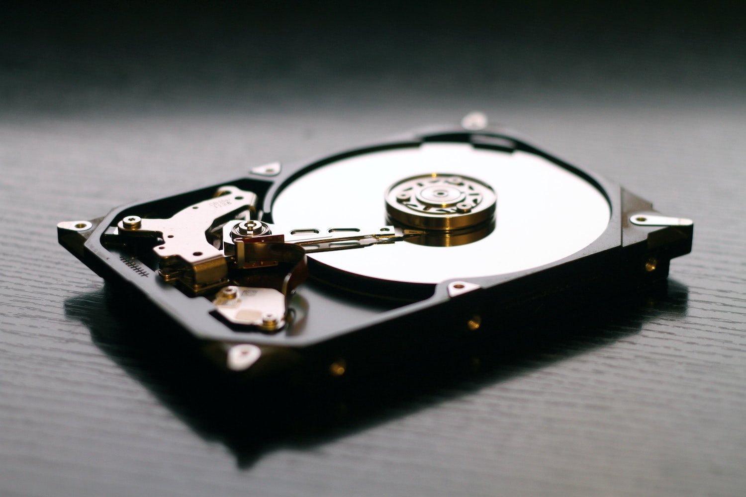
A while ago I posted my home storage server build which at the time was setup to run FreeNAS. Things have moved on in that space and FreeNAS has been replaced with TrueNAS Core. I thought I would post my FreeNAS to TrueNAS upgrade experience.
First off the recommendation is to ensure you’re on the latest FreeNAS version (the last official release, which was FreeNAS 11.3-U5). I had already been running this version for a while so I was set there.
FreeNAS to TrueNAS Upgrade Process
I started off by creating a full, manual backup of all my storage pools to an external disk. I verified a bunch of files in various locations on the backup disk to be extra sure they looked good.
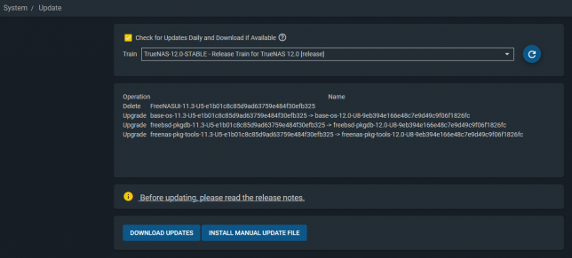
Next was to switch release trains to TrueNAS-12.0-STABLE. At the time of posting, the current release is TrueNAS-12.0-U8.
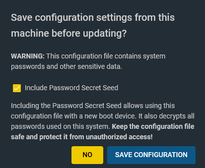
Clicking Download Updates started the download and upgrade process. Before starting you’re offered the chance to download your configuration backup. Definitely do this. It contains all your configuration as well as an optional password secret seed. This is important if you need to re-install the OS or change to a new boot device.
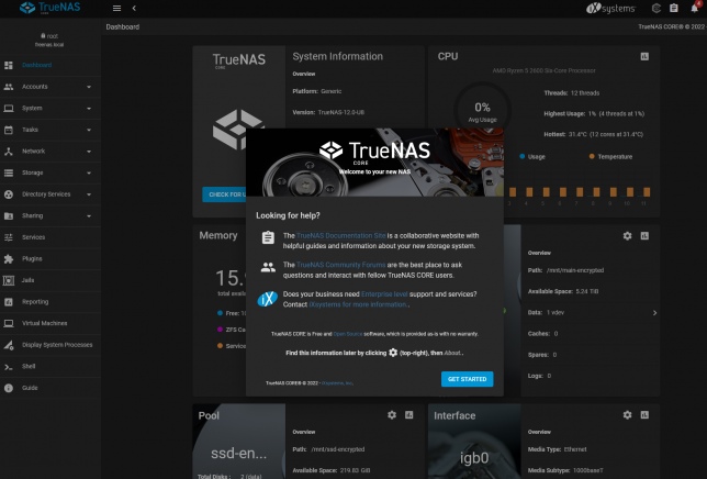
Once the upgrade completes the UI should reconnect after reboot, showing off the shiny new dashboard.
Updating ZFS Feature Flags
After verifying I could still access my SMB shares and that my NFS provisioner for my Kubernetes cluster was still working as expected I decided to lock in TrueNAS 12.0 by updating my ZFS pool feature flags across all zpools.
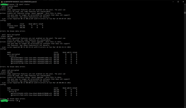
In a shell, I ran zpool status to take a look. Each pool is listed and should shows that some new features are not yet enabled. By leaving them as is, you retain the ability to roll back to your old FreeNAS version. Updating them locks you into the ZFS version that they were introduced with.
Updating to use the latest feature flags is something you should personally decide on. Do you need the newer feature flags?
According to this post, TrueNAS 12.0supports the Feature Flags listed below. (Bold are read-only backwards compatible, and italicized flags are very easy to return to the enabled state):
Allocation Classes
Bookmarks v2
Bookmark written
Sequential Rebuilds [device_rebuild]
Encryption
Large dnodes
Livelist
Log Spacemap
Project Quota
Redacted datasets
Redaction bookmarks
Resilver defer
Userobj accounting
zstd compression
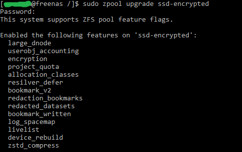
Updating ZFS feature flags is then as simple as running the zpool upgrade command.
E.g. sudo zpool upgrade my-pool
The last step is to upgrade any jails you might be running. Use the iocage upgrade command to get going with.
In the late ninetees, as a teenager I had the priveledge of owning a second hand Creative Labs 3dfx Voodoo 2 graphics card. It was an upgrade for my own hand-built PC – an AMD K6-2 333mhz system I had painstakingly saved up for and cobbled together.
Nostalgia running high, I recently set about building up a ‘retro’ gaming PC. With roughly the same specification as my original K6-2 machine from the late ninetees, it also features an original 3dfx Voodoo 2 accelerator card.
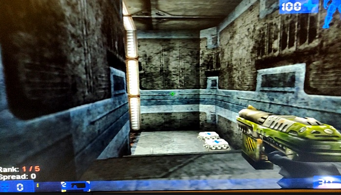
Unreal Tournament playing on my retro PC with the 3dfx Voodoo 2
The Brief Story of 3dfx Interactive and the Voodoo
A group of colleagues originally working together at SGI decided to break out and create 3dfx Interactive in San Jose, California (1994). This was after an initial failed attempt at selling rather pricey IrisVision boards for PCs.
Their original plan was to create specialist hardware solutions for arcade games, but they changed direction to instead design PC add-on boards. The reason for their pivot came about as a result of a few favourable factors. Namely:
The cost of RAM was low enough to make this a feasible endeavour.
RAM latency was much improved and allowed for ‘high’ clock speeds of up to 50MHz.
3D games were picking up in popularity. Spearheaded initially no doubt by id software with games such as Wolfenstein 3D, DOOM, the market was clearly headed to a point where 3D accelerated graphics would be in demand.
The first design, the SST1 (marketed as the Voodoo 1), targeted the $300-$400 price range for consumer PCs. A variety of OEMs picked up the design and released their own reference design boards, leading to the success of the original Voodoo line-up of 3D accelerator cards.
Enter the Voodoo 2
After the initial success of the Voodoo 1, the 3dfx Voodoo 2 (SST2) was soon born. It had vastly improved specifications over the original SST1 design such as:
100MHz clock rated EDO RAM (running at 90 MHz, 25 ns)
90MHz ASICs
2 x Texture Mapping Units (TMUs)
The fillrate of the Voodoo 2 was around 90 MPixels/s, and frame rates in benchmarks showed a massive uplift, nearly doubling in some cases.
My first (original) 3DFX Voodoo 2 PC Build
My first self-built (from scratch) PC was a bit of a frankenstein build. I had carefully budgeted and selected a motherboard that had onboard everything. Graphics, sound and networking. It would also run an AMD K6-2 CPU – a budget friendly option compared to Intel at that time.
The onboard graphics card shared 8MB of memory from system RAM (of which I only had 32MB total). As far as I recall it was capable of running Direct3D enabled games, albeit hobbling along with crippled frame rates.
Upgrading to a 3dfx Accelerator Card
After enduring this ‘fps hardship’ and learning more about the recently successful 3dfx graphics cards (a friend had a 4MB 3dfx Voodoo ‘1’ card), I found out about a second hand option. It was available through a friend of a friend, and would cost me 500.00 South African Rand (ZAR). This was a lot for a teen back then. I had saved up money, and bargained with my parents to combine my funds with a birthday gift contribution in order to purchase this card.
The Creative Labs 3D Blaster Voodoo 2. Mine came in almost identical packaging, but I had the 12MB version.
As I recall, I had to make massive concessions in order to fit the graphics card into my machine.
My motherboard only had 2 PCI slots. Both were horizontally in line with the CPU socket. The board design was probably never intended to house cards longer than the average PCI device at the time.
I had to remove the K6-2’s heatsink I was using and replace it with one from an older 486 machine that I had lying around. The profile of the 486 heatsink was much lower, allowing the 3dfx Voodoo 2 card to slot into a PCI slot, extending over the heatsink.
The problem now was that the 3dfx card’s lower PCB edge was now just about in direct contact with the heatsink. Another issue was that the heatsink was not made for mounting to a Socket 7 board. This forced me to lay my computer’s chassis down on it’s side in order for gravity to keep the heatsink in place!
I had a plan to keep pressure on the heatsink to maintain better contact with the CPU. Using a bit of non-conductive material between the 3dfx card’s PCB and the heatsink, I kept things in place. I also had to permanently angle a large fan blowing into the now open case.
This was the price I would pay to have my budget 3dfx voodoo 2 enabled system.
The Retro 3dfx Voodoo 2 PC Build
Recently after a bout of nostalgia and watching LGR videos, I started trawling eBay for old PC parts. The goal was to almost identically match my original PC build.
After a number of weeks of searching, I found the following parts. The motherboard was the most difficult to find (at a good price). Most Super Socket 7 boards I would find were dead and listed as spare parts.
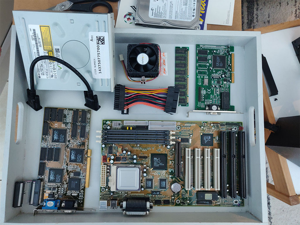
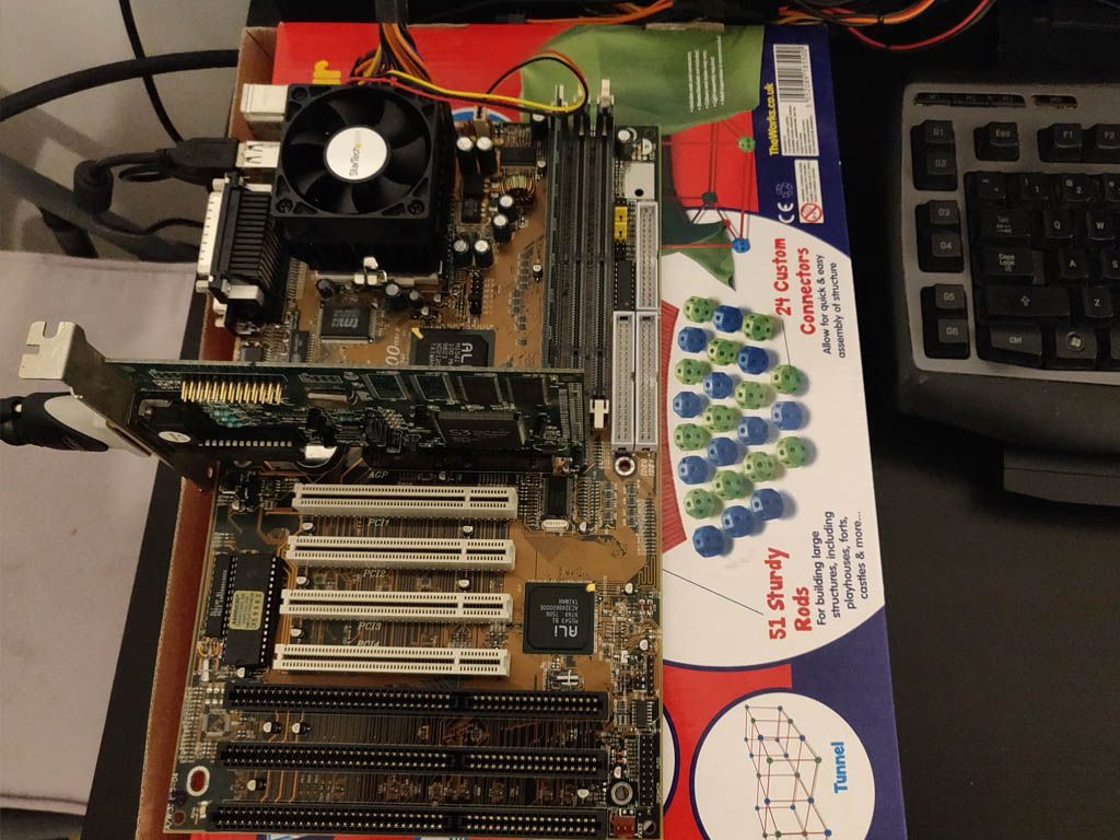
Most of the parts lined up and ready for the build.
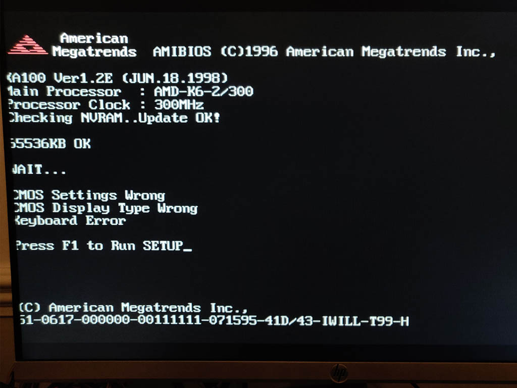
Iwill XA100 Aladdin V Super7 Motherboard, an AMD K6-2 300 CPU, and 64MB of PC100 SDRAM (168 pin)
S3 Trio 3D/2X graphics card (the Voodoo only handled 3D, and uses a loopback cable to plug into a ‘2D’ card)
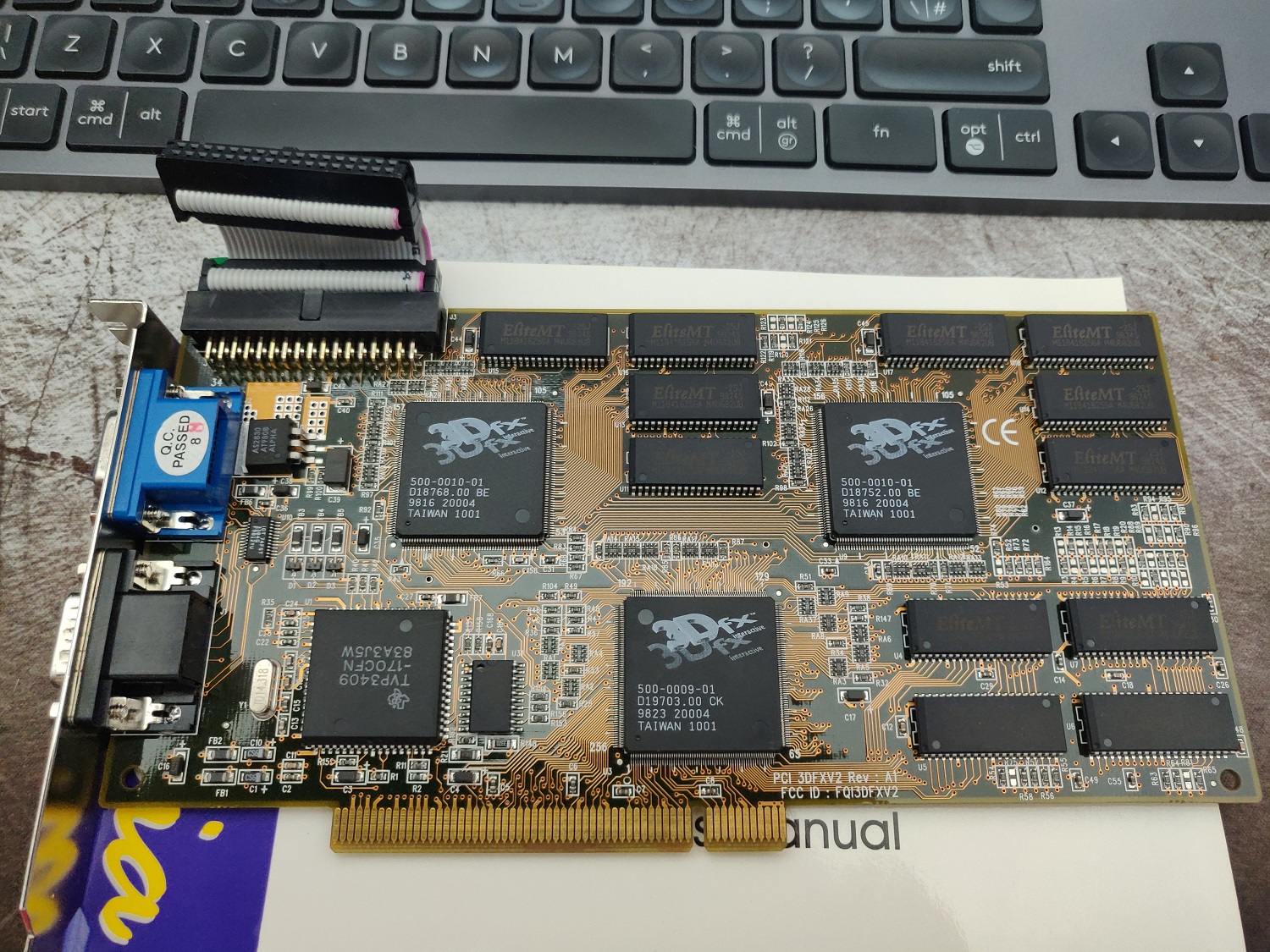
3DFX JoyMedia Apollo 3D fast II 12Mb Video Card PCI Voodoo2 3DFX V2 Rev A1
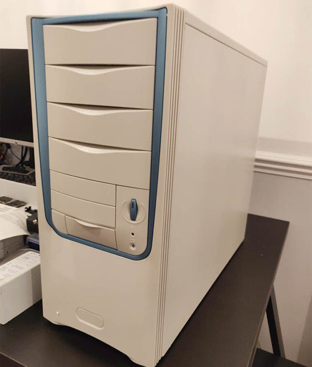
A Retro styled, beige ATX PC Chassis, Computer MIDI Tower Case
Creative Sound Blaster Live 5.1 Digital SB0220 PCI Sound Card
An 80GB IDE HDD, IDE ribbon cable, and an older DVD-R drive.
I used a modern 80 plus certified ATX power supply. It has a power connector with an older 20 pin layout which was perfect to re-use.
To test the hardware, I powered up the basic components on top of a cardboard box. Generally a good idea and especially so when using older hardware.
‘Bench’ test of the hardwareFirst POST successful, aside from USB keyboard not working (needed legacy option for USB enabled)The ‘retro’ looking MIDI tower chassis I got for the build
Gaming on the Retro PC Build
After digging out a CD burner and an old image of Windows 98 SE, I’ve got an operating system running and have installed drivers along with a bunch of games.
They play just as I remember. I’ve installed Quake, Quake 2, Unreal Tournament, and a few others to keep me busy for now.
Unreal Tournament in Glide 3dfx rendered mode.
The next step is to replace the temporary modern day LCD monitor I’m using right now. A period correct CRT monitor would really complete the build. I remember Samsung SyncMaster CRTs being excellent. My aim is pick one of these up to complete the system.
If you’re nostalgic like me and want to revisit the PC and games hardware of the late 1990s I highly recommend a build like this.
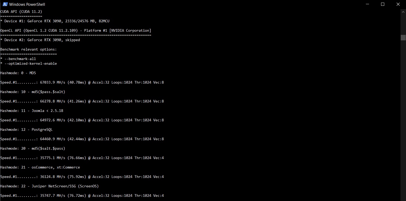
I picked up an nVidia RTX 3090 toward the end of last year. In hindsight, I was lucky to have purchased it early on soon after release. The GPU shortage has caused a massive spike in prices and this card is now worth double what I originally paid for it! Anyway, acquisition story aside, I was curious how it would perform in a Hashcat benchmark (all) run. Here are my Hashcat RTX 3090 benchmark results.
For a quick and easy run I’m using the hashcat 6.2.2 (Windows) binary.
.\hashcat.exe -b --benchmark-all
The performance seems on-par if not slightly higher than some other RTX 3090 benchmarks I have seen around. An impressive set of results.
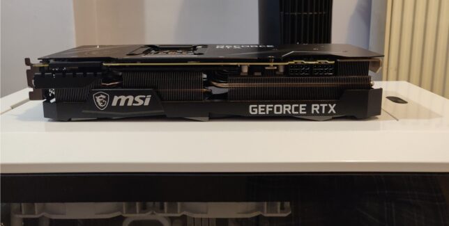
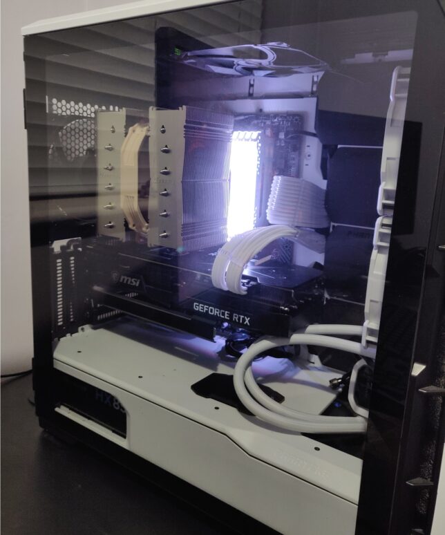
I am running the MSI GeForce RTX 3090 Ventus 3X OC 24GB model card. I upgraded from a GeForce 1080 Ti (12GB) model and the hashing speeds are way faster. The 3090 is a power hungry beast though. It gets hot and the fans are noisier than my 1080 Ti’s were. To ensure my system’s power delivery was up to the task, I also upgraded to a Seasonic Focus PX-850 850W 80+ Platinum at the same time.
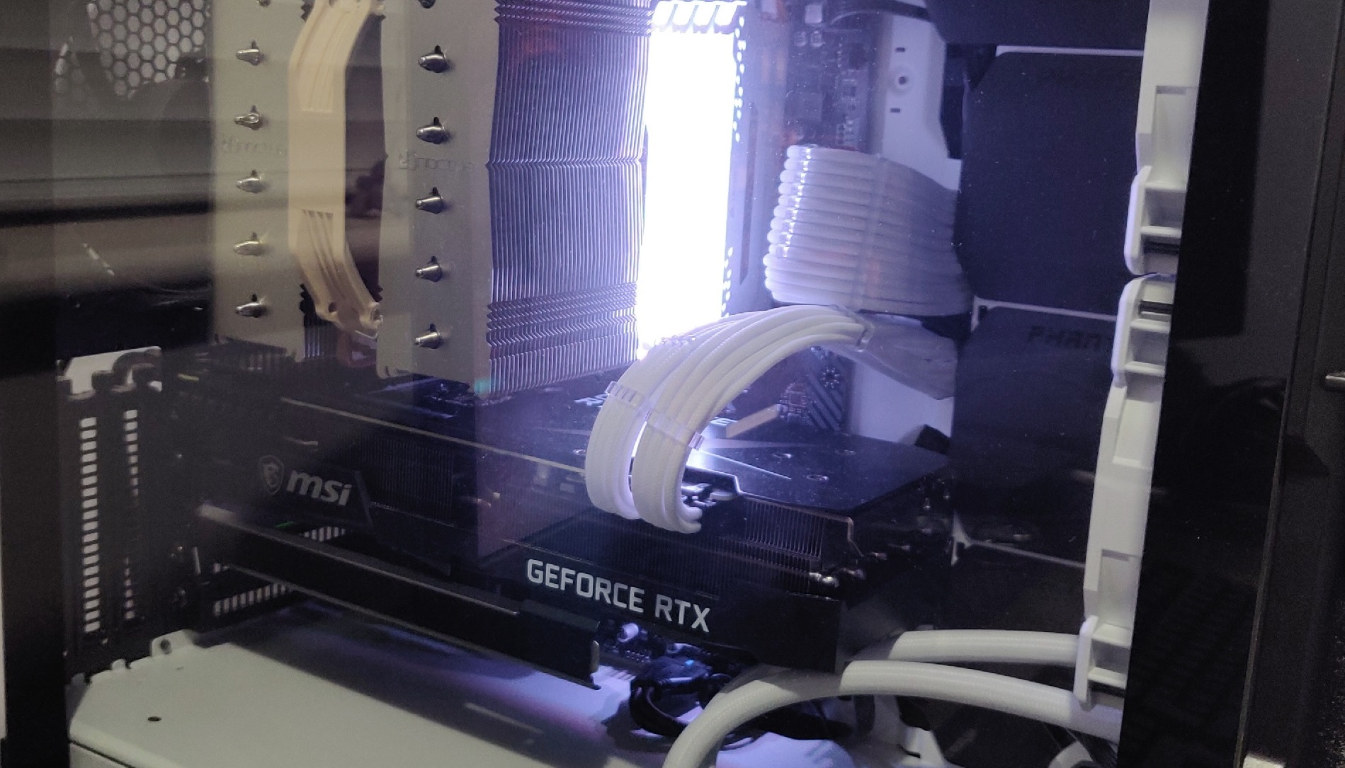
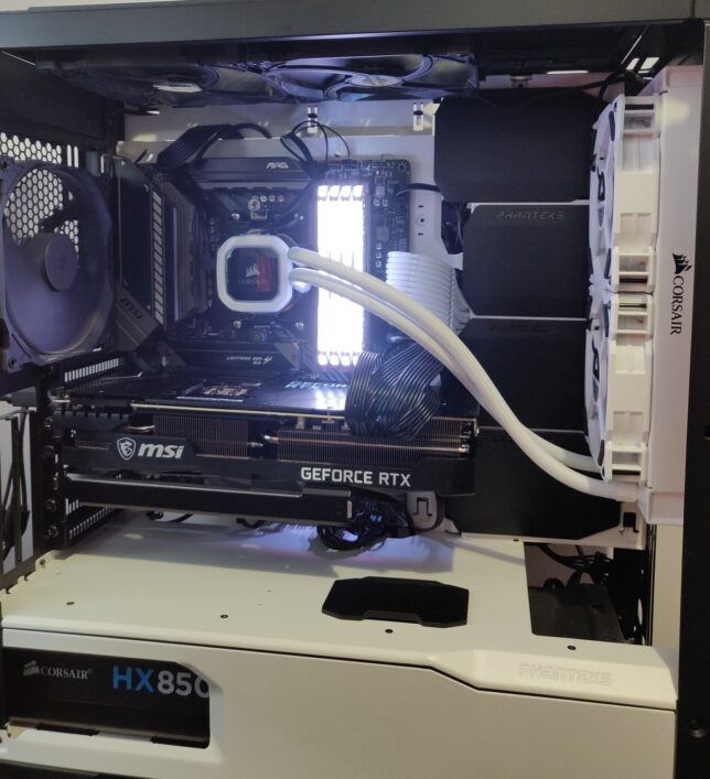
As for the PC build around the RTX 3090, here are a few photos…
You might notice an AIO installed, but not connected – I was in the process of testing a dual 240mm radiator (AIO) versus a high performing Noctua air cooler, so had left it in the chassis during transition.
I’ll see if I can run the same benchmark suite on my uBuntu install and update the results here. I have not tested the RTX 3090 card under this OS yet so I’m not sure if I’ll run into any driver issues or not.
Funny story of how I ended up with an RTX 3090 (it is a bit overkill!)…
Back in September or October of 2020 (I forget when the 3xxx series launch was), I had pre-ordered the MSI RTX 3080 at MSRP. I was 180 or so in the pre-order queue after months of already waiting. My queue position was barely changing week over week and I got impatient. I saw a handful of RTX 3090 cards come in stock at a local retailer and purchased one.
These cards would generally remain in stock for a few days due to everyone holding out for the much cheaper (at the time) RTX 3080 pre-order promises.
It was a lucky break for me, as those 3080 cards never came for most in that queue. GPU mining and GPU shortages made sure of that. Prices sky rocketed. Looking up this card now I see it costs almost double what I originally paid last year (if you can even get stock that is).
Now I just hope the card lasts at least a few years or more so I don’t ever have to worry about RMA and stock levels…
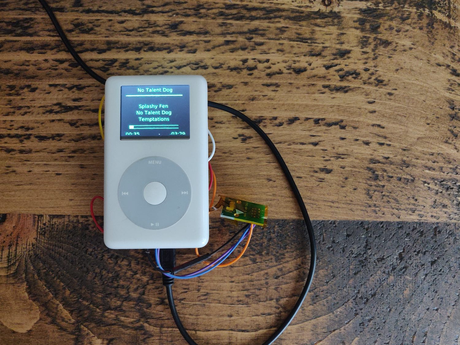
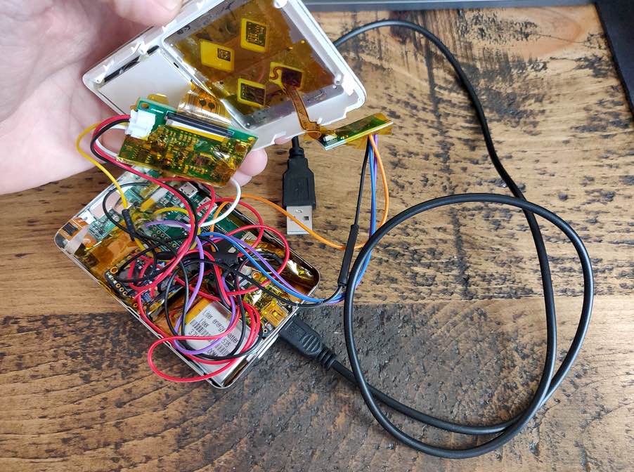
Here is my version, up and running, albeit with some hardware leaking out the side for now…
The main components required in terms of hardware are:
iPod Classic (4th gen) – at least the device case and clickwheel components
A Raspberry Pi Zero W
2″ LCD display (see note further on about an alternative)
3.7V 1000mah LiPo battery
Adafruit boost module (to boost 3.7V to 5V required by the Pi, LCD, etc…
Adafruit USB charge controller module
Once it’s all connected and configured, you’ll be able to load up your own Spotify playlists and libraries, browse them, and play them all from your iPod Classic device over a bluetooth speaker or remote system.
Some wire reduction still required before I can completely close it up.
SpotiPod High-level Build
I won’t be getting into the low-level parts of the build, so for specific details I would recommend viewing Guy’s project log and branching off the posts there.
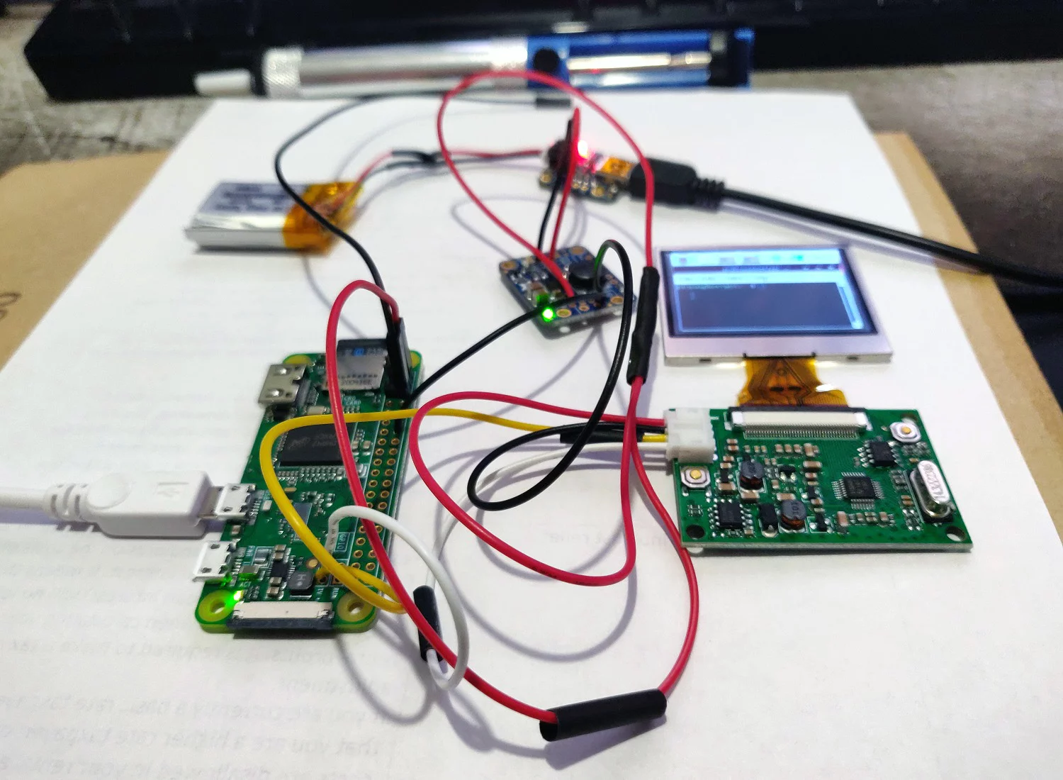
Initial Raspberry Pi Zero W setup with 2″ LCD display
I started off loading Raspbian Lite OS onto an 8GB microSD card and booting up a barebones Pi Zero W. The W version is important because it has WiFi and Bluetooth on the board.
My first task was to configure SSH to start automatically on boot. Useful when I have no display to start with. I also added some of the required software components to begin testing and messing around with, including redis server, compiling the click c++ application that Guy wrote to interface with the iPod’s clickwheel, and setting up some of the X11 components for a basic UI.
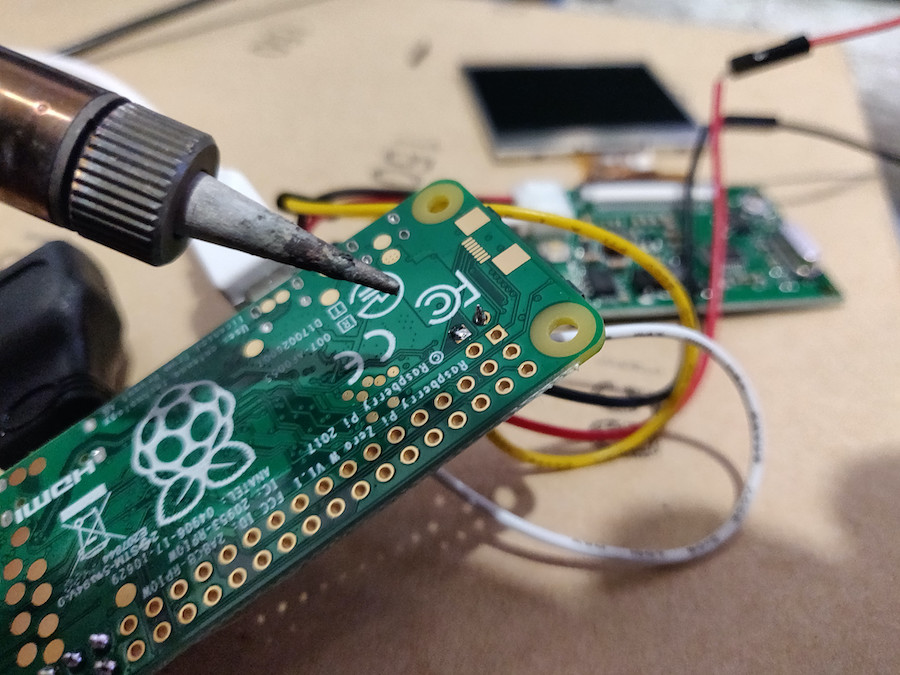
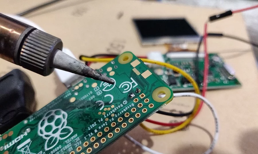
Soldering up the connection for the 2″ LCD display was my first hardware connection task. My soldering iron might come out once in a year, so I’m a bit of a novice in this area, but I managed the task on my first go.
Connecting the LCD to Raspberry Pi Zero via Composite ConnectorFirst LCD test successful
Connecting the Charge Controller and Voltage Boost Modules
Next up I focused on getting the power delivery working. The goal was to be able to charge the LiPo battery via USB and have the circuit supply 5V to all SpotiPod components where required.
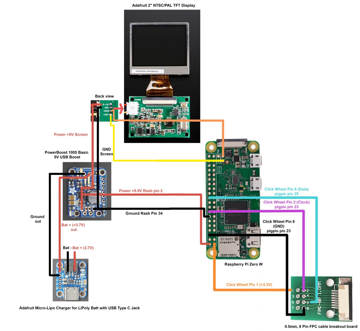
I familiarised myself with the Adafruit module documentation and pinout diagrams before connecting the circuit up.
Adafruit Powerboost 1000 module
Adafruit Charge Controller
Here is a useful diagram to follow, posted by Kakoub on the hackaday.io project page, re-hosted here in case the imgur upload ever disappears:
Click for a larger, clearer version
So after getting power delivery and connections soldered in place, and precariously placing all the components away from eachother to prevent shorts, here is where I was at:
Powerboost and Charge modules connected
Testing the Click wheel and Software
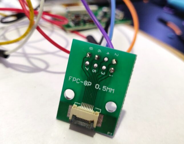
The click wheel connectivity is made easier with an 8 Pin FPC cable breakout board. I hooked this up next, soldering the 4 wires required for power and data.
The click wheel ribbon connector could then snap into the breakout board ribbon connector. This is by far the most delicate part of the build in my opinion. The ribbon cable is super thin and delicate.
Connecting the 8 pin FPC breakout board. My soldering skills slowly coming back with a bit of practice…
Testing the interface was a case of compiling the clickwheel program with gcc over an SSH connection then executing it with everything connected.
If wired up correctly, the program will output touch and click data to stdout.
iPod Classic click wheel testing over SSH
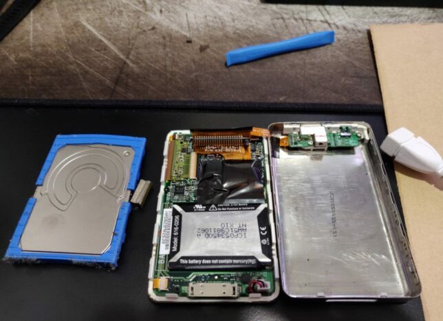
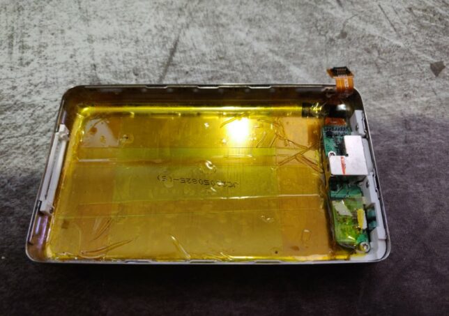
Gutting the old iPod Classic
I managed to snag an old iPod Classic 4th gen off eBay for about £20. It wasn’t working, but had the two bits I needed – the chassis, and the clickwheel.
Breaking out my trusty iFixit essentials toolkit, I set about opening it up to remove the unecessary components.
The method I found to work was to pry it open on the left and right edges using the pry tool. Once you can get into one of the edges, slide the tool around, and things get easier.
Insulating the case and components
With most of the electronics connected, I began insulating things with polyimide tape. Most importantly, the metal iPod case. I put down about three layers of tape and tried to cover all parts as best I could.
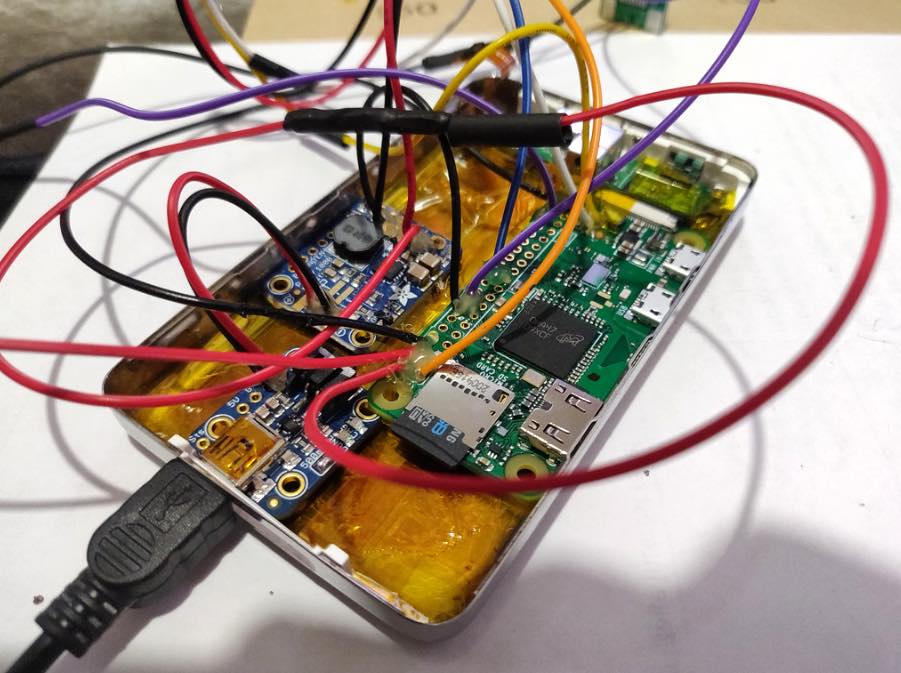
Installing into the iPod Classic Case
This is the tricky part. It’s quite difficult to squeeze all the SpotiPod hardware in.
I started out by strengthening all my soldering connections with a bit of hot glue.
Adding hot glue to the soldered connections
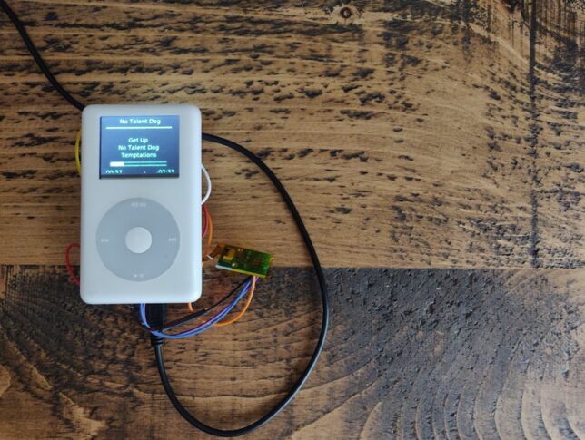
After a bit of arranging, squeezing, and coercing, everything fits… Mostly!
Things are still not perfect though. I need to reduce my wire lengths before I can get the case to fully close.
For now though, everything works and I have a fully functional SpotiPod!
Tips and Tricks
I’ve put together a list of things that might help if you do this yourself. These are bits that I recall getting snagged on:
Make sure you setup all the X11 and software dependencies correctly. Getting Openbox and the frontend application to launch on start up can be tricky and this is crucial. Pay attention to your /etc/X11/xinit/xinitrc and /etc/xdg/openbox/autostart configurations.
You don’t have to use the more expensive Adafruit composite LCD display. Ricardo’s build at RSFlightronics uses a much cheaper LCD and some creative approaches to get display output working.
Watch out for the click wheel ribbon orientation when you connect it to the breakout board!
Use thin and short length wires for connections where possible. Not too short though as it is useful to be able to open the device up and put the two halves side-by-side.
Make sure you have a Spotify Premium subscription. I can’t remember exactly, but I’m sure that creating your own app to get your client and secret keys, or some of the scopes required for the app will only work on Premium. (It might have even been spotify connect).
You’ll need to configure your own Spotify App using the Spotify Developer portal. Keep your client and secret keys safe to yourself. Remember to setup environment variables with these that the openbox session can access.
The frontend/UI application has a hardcoded reference to the Spotify Connect device as “Spotifypod”. Keep things simple by setting your raspotify configuation to use this name too, otherwise you need to update the code too.
If you’re struggling to get the software side working at first, it can really help to setup VNC while you debug things. This allows you to get a desktop environment on the Pi Zero and execute scripts or programs in an x session as openbox would.
Thanks again to Guy Dupont for his excellent SpotiPod project and idea. Putting this all together really makes for a fun and rewarding hardware/software hacking experience.
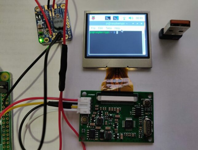
This display is ridiculously small. It’s quite something to boot up Raspbian with the PIXEL desktop environment on a Pi Zero with this little 2″ display.
Ground (ground connected to pin 14 / ground on Pi Zero and negative on the boost module)
Positive (yellow) from TFT display board to TV on the Pi Zero
White from the TFT display board to the other pin, next to the TV pin.
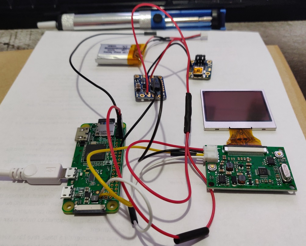
Here’s what everything looked like after connecting the boost module (3.7v to 5v conversion), the battery charge controller, LiPo, and 2″ TFT display.
Powering up and Configuration
Power up and enjoy the tiny display outputting the boot up sequence.
The display is meant to run at 320×240, so after booting up I edited /etc/config.txt to set this up along with some overscan tweaks.
sudo nano /etc/config.txt
Set the following in the /boot/config.txt file:
# these overscan settings are what worked well for me
overscan_left=-26
overscan_right=-26
overscan_top=-16
overscan_bottom=-24

framebuffer_width=320
framebuffer_height=240
Although it is really expensive for what it is, the 2.0″ TFT display is great for small electronics projects that call for full display output. It’s simple and easy to connect, and doesn’t take up too much space either.