I picked up a Puck.js a while ago and after trying out a few basic bits of code, sadly let it start to gather dust on my shelf. That changed this weekend as I browsed the sample project listings for something simple to build, picking up the Puck.js Duplo police siren build to try.
It should be a fun toy for my youngest to play with, as he really enjoys Duplo.
What is the Puck.js?
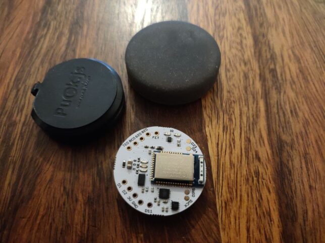
The Puck.js and it’s button case.
The Puck.js is an open source JavaScript microcontroller. It has a variety of features such as:
Button
Magnetometer
Accelerometer
Gyro
IR & RGB LEDs
Temperature and light sensor
FET output
Programmable NFC tag
9 IO pins
The best part about the Puck.js for me is how accessible it is to run and deploy code to. Using Web Bluetooth and it’s included puck.js library, you can write code in a Web IDE, connect over Bluetooth, and have your code running in seconds.
Building the Puck.js Duplo Police Siren Project
If you want to try it out yourself, the actual tutorial page itself is the best resource to begin with. There is a video available there to follow along with.
Here is the Thingiverse page where you can get the model. It currently only lists a scad version of the file, so you’ll need to download OpenSCAD and open it there.
Here is a gist for the file including the cut-out operation that subtracts the innards from the block to make room for the puck.js and piezo to fit into.
I printed the block using my Elegoo Mars resin 3D printer. My first go seems to be slightly loose fitting, so I might shrink the model to 99% size and try again for a second iteration.
I used a new resin that is meant to be easily rinsed/washed after printing with water. The quality on the top of the block doesn’t look as good as usual, so I’m not sure if this resin is to blame for that or not.
Connecting the Components
The LEDs connect to D1/D2 and D30/D31. The piezo goes on D28/D29. I used RGB LEDs, so I snipped the other legs off, leaving just the blue and common cathode terminals to connect up.
After a bit of dodgy soldering, it works!
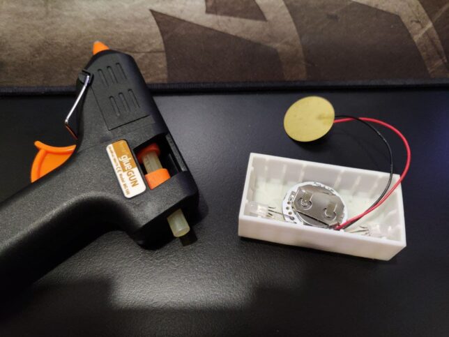
Installing Everything Into the Block
With a little bit of coercion, the whole lot fits in. I used a bit of hot glue on four edges of the Puck.js to keep it in place, but keep it easy to remove if needed.
After that, I added a layer of scrap paper with the piezo in-between, and glued that in too.
Here is the final result.
The Puck.js may be fairly pricey, but it includes a lot of IO. It’s battery and use of Bluetooth LE make it ideal for projects where battery life is a concern. The battery is super cheap and can last up to around a year if used carefully.
I had fun making this project. It’s a great project to get started with the Puck.js, and hopefully I’ll find some more use cases soon where I can use more of these great little devices.
I recently invested in a standing desk for my home office. On the recommendation of a friend, I purchased the Jarvis Laminate Standing Desk from fully.com.
I’ve been working predominantly from home for around 1.5 years now (at least 4 days a week), and since going fully remote at 5 days a week after COVID-19 I decided to invest more in the home office.
After having noticed myself slouching at my desk on more than one occasion, I got curious about standing desks. After reading about the apparent benefits of standing more (as opposed to sitting at a desk all day), and on the recommendation of a friend I pulled the trigger on this fully motorised setup.
Here are the specifications and complete configuration I went for:
Jarvis Laminate Standing Desk (160 x 80 cm, black finish)
Jarvis Lifting Column, Mid Range
Jarvis Frame EU, Wide, Long Foot Programmable
WireTamer Cable Trays (2x)
Topo Mini Anti-fatigue mat
The total for the desk parts and standing mat came up to around £600 excluding VAT, which I think is a great price considering the health benefits it should bring about over the longer term.
The build
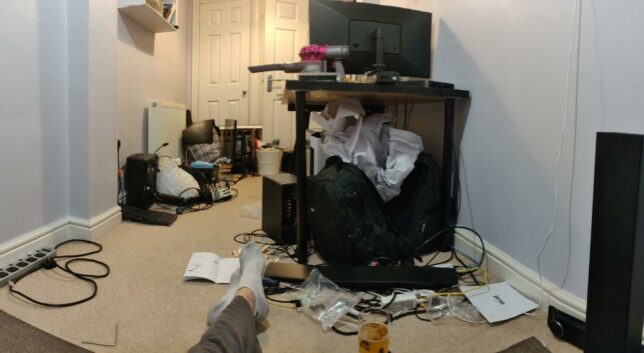
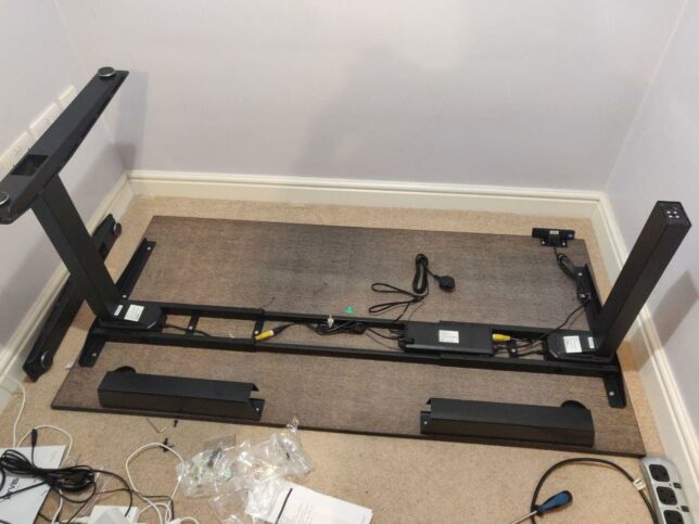
I got stuck in one evening after work, and thought it might be 2 hour job. I was very wrong. Here is photo I took of the chaos I unleashed in the office after taking down my old desk and beginning assembly of the Jarvis.
Note the crossed legs, socks, and beer as I take a breather, almost admitting defeat for the night.
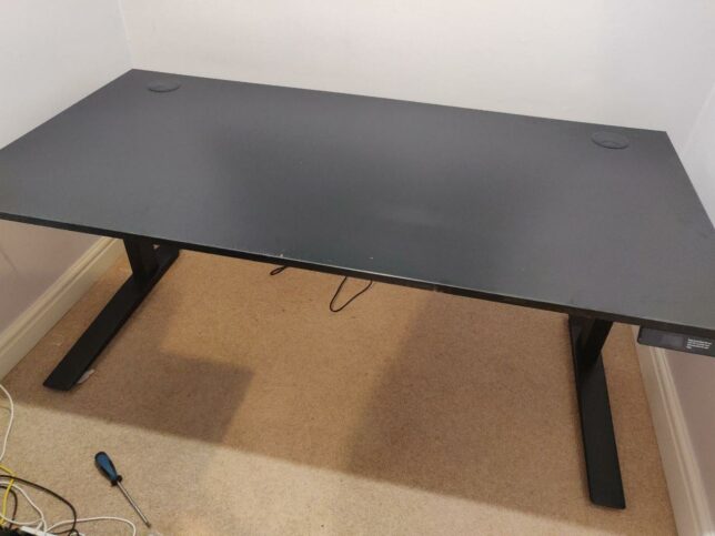
Soon I was making progress though.
Multi-monitor configuration
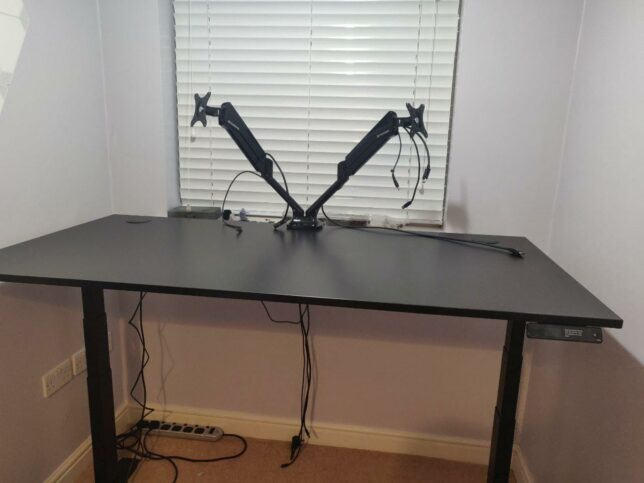
I’ve got two computers that needed setting up. One is my PC, the other is an Apple Mac Mini (the main work machine). So next on the list was a decent adjustable multi-monitor stand. I ended up getting:
FLEXIMOUNTS F6D Dual monitor mount LCD arm
This was the strongest arm I could find. I could not (at the time) find anything that would fit my 34″ Acer Predator ultra wide LCD. (It’s pretty heavy).
Although this mount is only compatible up to 30″ LCDs, it seems to cope with my Acer Predator on one side, and my LG 5K Retina 27″ LCD display on the other.
Around midnight that evening I finally had everything configured and in order. I booted up both machines and raised the desk to try it out.
Adjusting to, and actually working at the desk
I’m not fully committed to standing all day (at least not yet). I tend to spend around 3 hours standing each day, and the remainder sitting. I’m slowly increasing the standing time as I go on.
The Top Mini anti-fatigue mat definitely helps. I also noticed wearing my light, minimalist running shoes feels good while standing and working too.
The topo mini mat
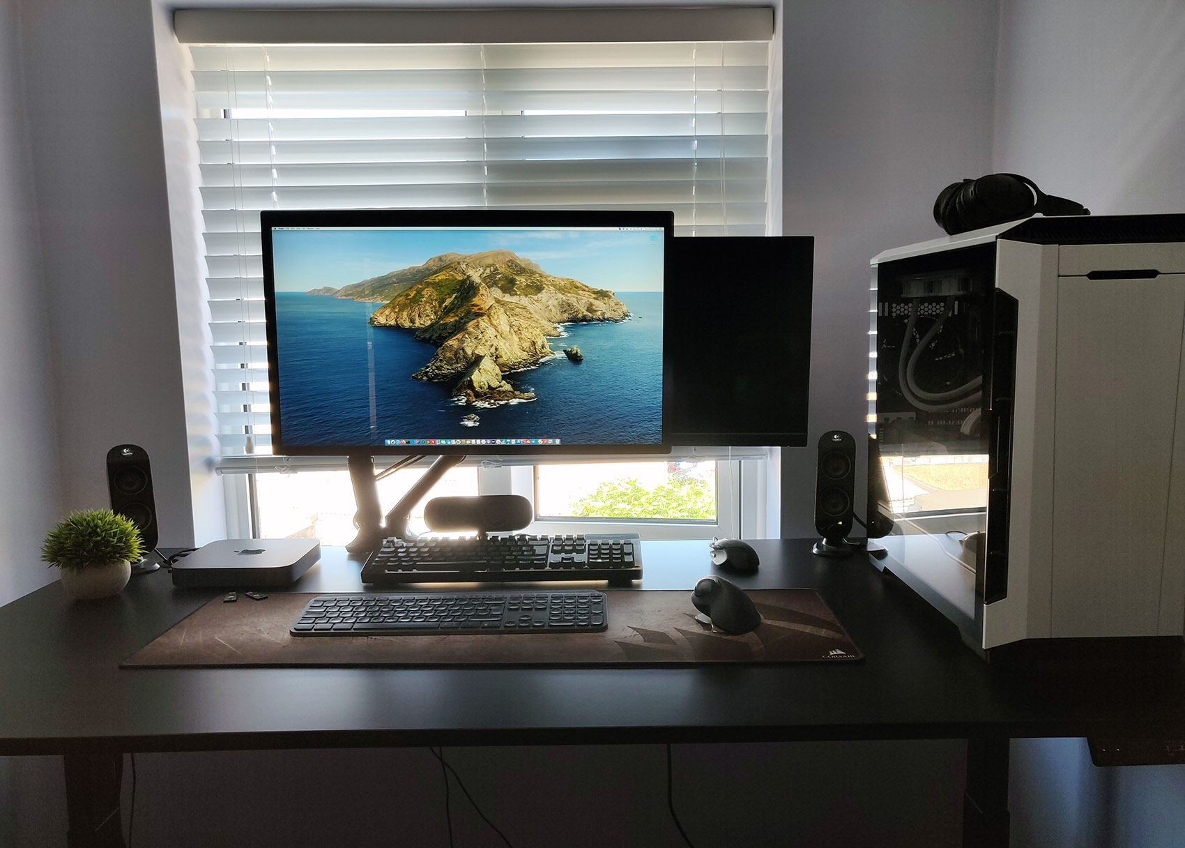
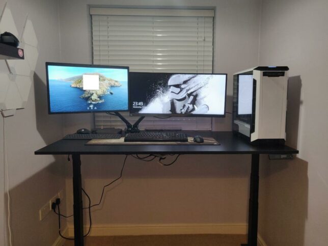
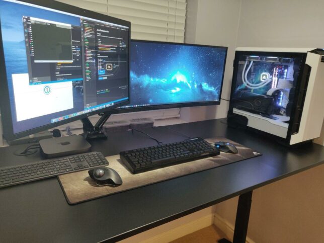
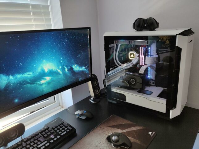
Some more angles of the full setup
Lastly, here are some photos of the final setup. Certainly a farcry and total overhaul since the days of this home office setup of mine circa 2009!
In summary, I’m very happy with the new setup. My office is a little narrow and crammed, but this configuration helps me move around a lot more and I feel better for it.
This is the third post in this series and the focus will be on completing the Raspberry Pi Kubernetes cluster by adding a worker node. You’ll also setup a software based load-balancer implementation designed for bare metal Kubernetes Clusters by leveraging MetalLB.
Here are some handy links to other parts in this blog post series:
By now you should have 1 x Pi running as the dedicated Pi network router, DHCP, DNS and jumpbox, as well as 1 x Pi running as the cluster Master Node.
Of course it’s always best to have more than 1 x Master node, but as this is just an experimental/fun setup, one is just fine. The same applies to the Worker nodes, although in my case I added two workers with each Pi 4 having 4GB RAM.
Joining a Worker Node to the Cluster
Start off by completing the setup steps as per the Common Setup section in Part 2 with your new Pi.
Once your new Worker Pi is ready and on the network with it’s own static DHCP lease, join it to the cluster (currently only the Master Node) by using the kubeadm join command you noted down when you first initialised your cluster in Part 2.
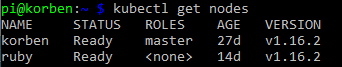
After a few moments, SSH back to your master node and run kubectl get nodes. You should see the new worker node added and after it pulls down and starts the weave net CNI image it’s status will change to Ready.
Setting up MetalLB
The problem with a ‘bare metal’ Kubernetes cluster (or any self-installed, manually configured k8s cluster for that matter) is that it doesn’t have any load-balancer implementation to handle LoadBalancer service types.
When you run Kubernetes on top of a cloud hosting platform like AWS or Azure, they are backed natively by load-balancer implementations that work seamlessly with those cloud platform’s load-balancer services. E.g. classic application or elastic load balancers with AWS.
However, with a Raspberry Pi cluster, you don’t have anything fancy like that to provide LoadBalancer services for your applications you run.
MetalLB provides a software based implementation that can work on a Pi cluster.
Install version 0.8.3 of MetalLB by applying the following manifest with kubectl:
Update the addresses section to use whichever range of IP addresses you would like to assign for use with MetalLB. Note, I only used 10 addresses as below for mine.
Apply the configuration:
kubectl apply -f ./metallb-config.yaml
Setup Helm in the Pi Cluster
First of all you’ll need an ARM compatible version of Helm. Download it and move it to a directory that is in your system PATH. I’m using my Kubernetes master node as a convenient location to use kubectl and helm commands from, so I did this on my master node.
Note: it uses a custom image from jessestuart/tiller (as this is ARM compatible). The command also replaces the older api spec for the deployment with the apps/v1 version, as the older beta one is no longer applicable with Kubernetes 1.16.
Deploy an Ingress Controller with Helm
Now that you have something to fulfill LoadBalancer service types (MetalLB), and you have Helm configured, you can deploy an NGINX Ingress Controller with a LoadBalancer service type for your Pi cluster.
If you list out your new ingress controller pods though you might find a problem with them running. They’ll likely be trying to use x86 architecture images instead of ARM. I manually patched my NGINX Ingress Controller deployment to point it at an ARM compatible docker image.
kubectl set image deployment/nginx-ingress-controller nginx-ingress-controller=quay.io/kubernetes-ingress-controller/nginx-ingress-controller-arm:0.26.1
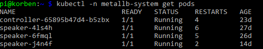
After a few moments the new pods should now show as running:
Now to test everything, you can grab the external IP that should have been assigned to your NGINX ingress controller LoadBalancer service and test the default NGINX backend HTTP endpoint that returns a simple 404 message.
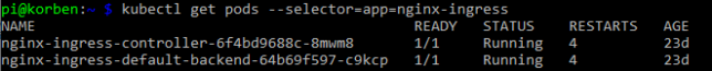
List the service and get the EXTERNAL-IP (this should sit in the range you configured MetalLB with):
kubectl get service --selector=app=nginx-ingress
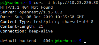
Curl the NGINX Ingress Controller LoadBalancer service endpoint with a simple GET request:
curl -i http://10.23.220.88
You’ll see the default 404 not found response which indicates that the controller did indeed receive your request from the LoadBalancer service and directed it appropriately down to the default backend pod.
Concluding
At this point you’ve configured:
A Raspberry Pi Kubernetes network Router / DHCP / DNS server / jumpbox
Kubernetes master node running the master components for the cluster
Kubernetes worker nodes
MetalLB load-balancer implementation for your cluster
Helm client and Tiller agent for ARM in your cluster
NGINX ingress controller
In part 1, recall you setup some iptables rules on the Router Pi as an optional step?
These PREROUTING AND POSTROUTING rules were to forward packets destined for the Router Pi’s external IP address to be forwarded to a specific IP address in the Kubernetes network. In actual fact, the example I provided was what I used to forward traffic from the Pi router all the way to my NGINX Ingress Controller load balancer service.
Revisit this section if you’d like to achieve something similar (access services inside your cluster from outside the network), and replace the 10.23.220.88 IP address in the example I provided with the IP address of your own ingress controller service backed by MetalLB in your cluster.
Also remember that at this point you can add as many worker nodes to the cluster as you like using the kubeadm join command used earlier.
The Kubernetes Master node is one that runs what are known as the master processes: The kube-apiserver, kube-controller-manager and kube-scheduler.
In this post we’ll go through some common setup that all nodes (masters and workers) in your cluster should get, and then on top of that, the specific setup that will finally configure a single node in the cluster to be the master.
If you would like to jump to the other partes in this series, here are the links:
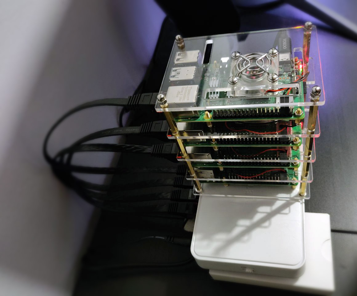
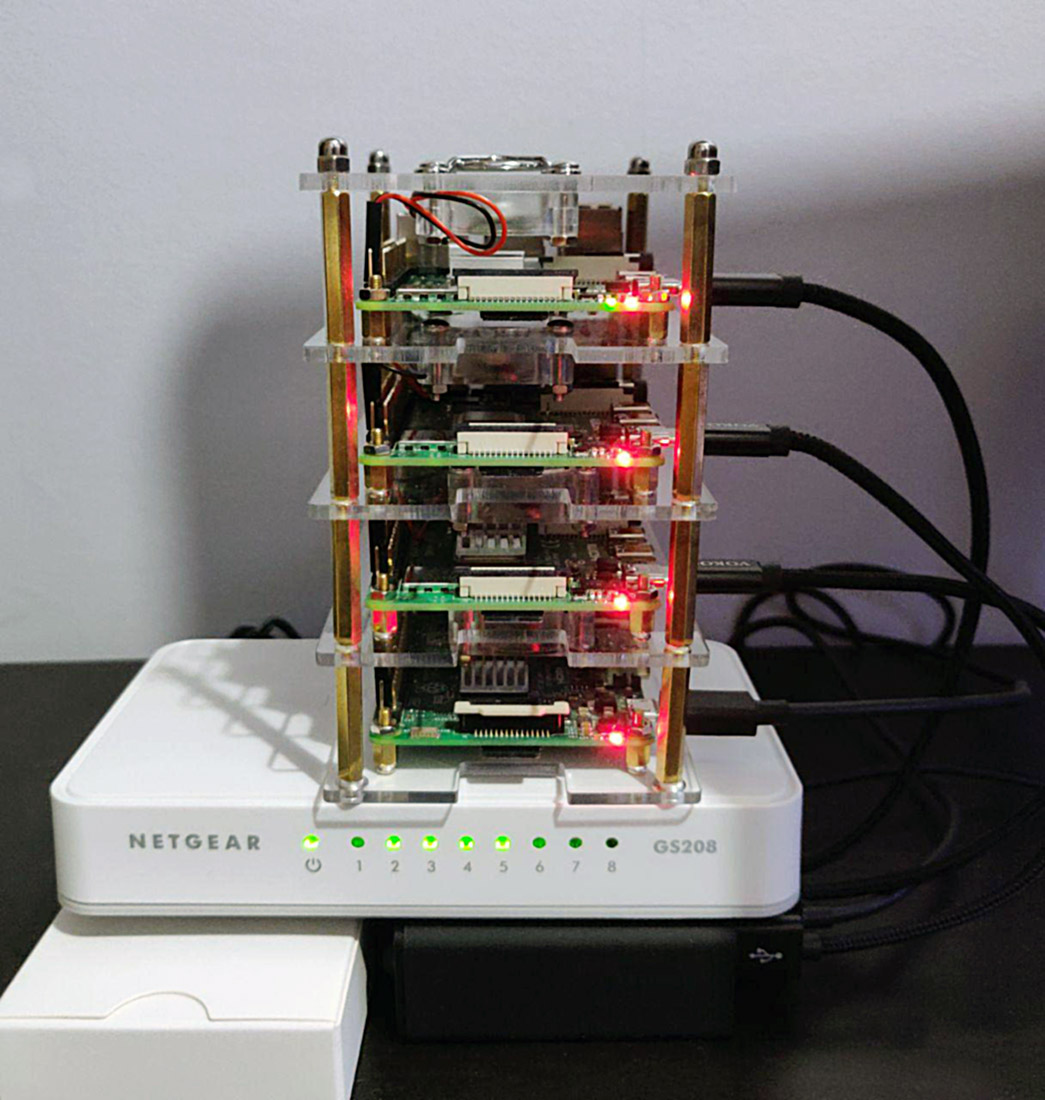
By now you should have some sort of stack or collection of Raspberry Pis going. As mentioned in the previous post, I used a Raspberry Pi 3 for my router/dhcp server for the Kubernetes Pi Cluster network, and Raspberry Pi 4’s with 4GB RAM each for the master and worker nodes. Here is how my stack looks now:
The stack of Rasperry Pi’s in my cluster. Router Pi at the bottom, master and future worker nodes above. They’re sitting on top of the USB power hub and 8 port gigabit network switch
Common Setup
This setup will be used for both masters and workers in the cluster.
Start by writing the official Raspbian Buster Lite image to your microSD card. (I used the 26th September 2019 version), though as you’ll see next I also updated the Pi’s firmware and OS using the rpi-update command.
After attaching your Pi (master) to the network switch, it should pick up an IP address from the DHCP server you setup in part 1.
SSH into the Pi and complete the basic setup such as setting a hostname and ensuring it gets a static IP address lease from DHCP by editing your dnsmasq configuration (as per part 1).
Note: As the new Pi is running on a different network behind your Pi Router, you can either SSH into your Pi Router (like a bastion host or jump box) and then SSH into the new Master Pi node from there.
Now update it:
sudo rpi-update
After the update completes, reboot the Pi.
sudo reboot now
SSH back into the Pi, then download and install Docker. I used version 19.03 here, though at the moment it is not ‘officially’ supported.
export VERSION=19.03
curl -sSL get.docker.com | sh && sudo usermod pi -aG docker && newgrp docker
Kubernetes nodes should have swap disabled, so do that next. Additionally, you’ll enable control groups (cgroups) for resource isolation.
Installing kubeadm and other Kubernetes components
Next you’ll install the kubeadm tool (helps us create our cluster quickly), as well as a bunch of other components required, such as the kubelet (the main node agent that registers nodes with the API server among other things), kubectl and the kubernetes cni (to provision container networking).
Next up, install the legacy iptables package and setup networking so that it traverses future iptables rules.
Note: when I built my cluster initially I discovered problems with iptables later on, where the kube-proxy and kubelet services had trouble populating all their required iptables rules using the pre-installed version of iptables. Switching to legacy iptables fixed this.
The error I ran into (hopefully those searching it will come across this post too) was:
proxier.go:1423] Failed to execute iptables-restore: exit status 2 (iptables-restore v1.6.0: Couldn't load target `KUBE-MARK-DROP':No such file or directory
Setup iptables and change it to the legacy version:
Lastly to finish off the common (master or worker) node setup, reboot.
sudo reboot now
Master Node Setup
Now you can configure this Pi as a master Kubernetes node. SSH back in after the reboot and pull down the various node component docker images, then initialise it.
Important: Make sure you change the 10.0.0.50 IP address in the below code snippet to match whatever IP address you reserved for this master node in your dnsmasq leases configuration. This is the IP address that the master API server will advertise out with.
Note: In my setup I am using 192.168.0.0./16 as the pod CIDR (overlay network). This is specifically to keep it separate from my internal Pi network of 10.0.0.0/8.
sudo kubeadm config images pull -v3
sudo kubeadm init --token-ttl=0 --apiserver-advertise-address=10.0.0.50 --pod-network-cidr=192.168.0.0/16

# capture text and run as normal user. e.g.:
# mkdir -p $HOME/.kube
# sudo cp -i /etc/kubernetes/admin.conf $HOME/.kube/config
# sudo chown $(id -u):$(id -g) $HOME/.kube/config
Once the kubeadm commands complete, the init command will output a bunch of commands to run. Copy and enter them afterwards to setup the kubectl configuration under $HOME/.kube/config.
You’ll also see a kubeadm join command/token. Take note of that and keep it safe. You’ll use this to join other workers to the cluster later on.
You’ll setup Weave Net next. At a high level, Weave Net creates a virtual container network that connects your containers that are scheduled across (potentially) many different hosts and enables their automatic discovery across these hosts too.
Kubernetes has a pluggable architecture for container networking, and Weave Net is one implementation of this.
Note: the command below assumes you’re using an overlay/container network of 192.168.0.0/16. Change this if you’re not using this range.
After a few moments waiting for your node to pull down the weave net container images, check that the weave container(s) are running and that the master node is showing as ready. Here is how that should look…
kubectl -n kube-system get pods
kubectl get nodes
pi@korben:~ $ kubectl -n kube-system get pods | grep weave
weave-net-cfxhr                  2/2     Running   20         10d
weave-net-chlgh                  2/2     Running   17         23d
weave-net-rxlg8                  2/2     Running   13         23d

pi@korben:~ $ kubectl get nodes
NAME     STATUS   ROLES    AGE   VERSION
korben   Ready    master   23d   v1.16.2
That is pretty much it for the master node setup. You now have a single master node running the Kubernetes master components / API server, and have even used to successfully provision and configure container networking.
As a result of deploying Weave Net, you now have a DaemonSet that will ensure that any new node that joins the cluster will automatically get the Weave Net CNI. All other nodes in the cluster will automatically update to ‘know’ about the new node and subsequently containers in the cluster will be able to talk to each other over the overlay network.
First off, here is a list of parts I used to set everything up:
1 x Raspberry Pi 3 (1GB) device for the router (this maintains a WiFi connection to my home network using the built-in WiFi and routes between this and the Ethernet device (eth0) which joins it to the Kubernetes network
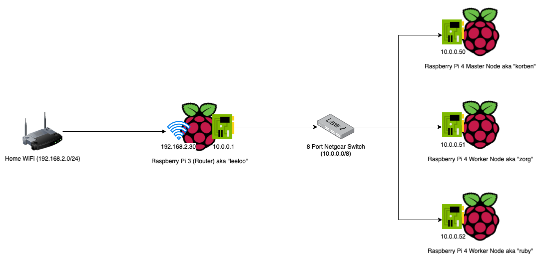
To make the setup as portable as possible, and also slightly seggregated from my home network, I used the 1 x Raspberry Pi 3 device I had as a router between my home network and my Kubernetes Layer 2 Network (effectively the devices on the 8 port Netgear Switch).
Here is a network diagram that shows the setup.
Building the Raspberry Pi Cluster Router
Of course you’ll need an OS on the microSD card for each Raspberry Pi you’re going to be using. I used the latest Raspbian Buster Lite image from the official Raspbian Downloads page (September 26).
This is a minimal image and is exactly what we need. You’ll need to write it to your microSD card. There are plenty tutorials out there on doing this, so I won’t cover it here.
One piece of advice though, would be to create a file called “ssh” on the imaged card filesystem after writing the image. This enables you to SSH on directly without the need to connect up a screen and setup the SSH daemon yourself. Basically just login to your home network DHCP server and look for the device once it boots then SSH to it’s automatically assigned IP address.
Also, it would be wise to reserve an IP address on your home network’s DHCP service for your Pi Router. Grab the MAC address of your Pi and add it to your home network DHCP service’s reserved IP addresses. I set mine to 192.168.2.30 on my WiFi network.
List the wlan interface’s MAC address with:
ifconfig wlan0
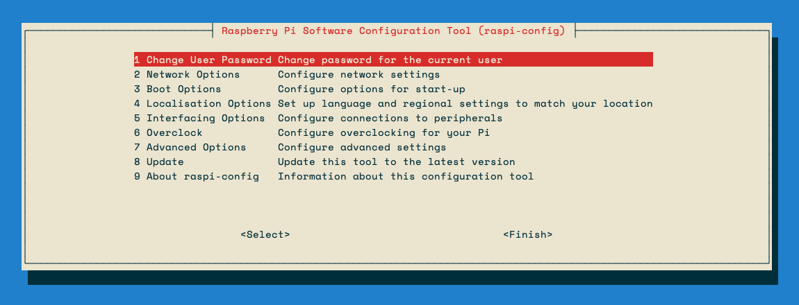
Setting Hostname and Changing the Default Password
On the Router Raspberry Pi, run the following command to change the hostname to something other than “raspberry” and change the default password too:
sudo raspi-config
Setting up the Pi Router
Now the rest of the guide deserves much credit to this blog post, however, I did change a few things on my setup, as the routing was not configured 100% correctly to allow external access to services on the internal Kubernetes network.
I needed to add a couple of iptables rules in order to be able to access my Ingress Controller from my home network. More on that later though.
Interface Setup
You need to configure the WiFi interface (wlan0) and the Ethernet Interface (eth0) for each “side” of the network.
Edit the dhcpd.conf file and add an eth0 configuration right at the bottom, then save.
Of course replace the above DNS servers with whichever you prefer to use. I’ve used Cloudflare and OpenDNS ones here.
Next, setup your WiFi interface to connect to your home WiFi. WiFi connection details get saved to /etc/wpa_supplicant/wpa_supplicant.conf but it is best to use the built-in configuration tool (raspi-config) to do the WiFi setup.
sudo raspi-config
Go to Network Options and enter your WiFi details. Save/Finish afterwards.
Create a new /etc/dnsmasq.conf file with the below command:
The script is the main dnsmasq configuration that sets DHCP up over the eth0 interface (for the 10.0.0.0/8 network side) and configures some nameservers for DNS as well as a few other bits.
Edit the service file for dnsmasq (/etc/init.d/dnsmasq) to prevent issues with start-up order of dnsmasq and dhcpcd:
sudo nano /etc/init.d/dnsmasq
Change the top of the file to look like this:
#!/bin/sh

# Hack to wait until dhcpcd is ready
sleep 10

### BEGIN INIT INFO
# Provides:       dnsmasq
# Required-Start: $network $remote_fs $syslog $dhcpcd
# Required-Stop:  $network $remote_fs $syslog
# Default-Start:  2 3 4 5
# Default-Stop:   0 1 6
# Description:    DHCP and DNS server
### END INIT INFO
The lines changed above are the sleep 10 command and the Required-Start addition of $dhcpcd.
At this point its a good idea to reboot.
sudo reboot now
After the reboot, check that dnsmasq is running.
sudo systemctl status dnsmasq
Setup iptables
First of all, enable IP forwarding. Edit the /etc/sysctl.conf file and uncomment this line:
net.ipv4.ip_forward=1
This enables us to use NAT rules with iptables.
Now you’ll configuring some POSTROUTING and FORWARD rules in iptables to allow your Raspberry Pi devices on the 10.0.0.0/8 network to access the internet via your Pi Router’s wlan0 interface.
sudo iptables -t nat -A POSTROUTING -o wlan0 -j MASQUERADE
sudo iptables -A FORWARD -i wlan0 -o eth0 -m state --state RELATED,ESTABLISHED -j ACCEPT
sudo iptables -A FORWARD -i eth0 -o wlan0 -j ACCEPT
Optional Step
This is optional, and you might only need to do this later on once you start running services in your Kubernetes Pi Cluster.
Forward Traffic from your home network to a Service or Node IP in your Cluster Network:
The above assumes a couple of things that you should change accordingly (if you use this optional step):
You have a Service running in the Kubnernetes network, listening on port 80 (http) on IP 10.23.220.88
You setup your Pi Router to use 10.0.0.1 as the eth0 device IP (as per above in this post), and your wlan0 interface is the connection that your Pi router is using to connect to your home network (WiFi).
You actually want to forward traffic hitting your Pi Router (from the WiFi wlan0 interface) through the 10.0.0.1eth0 interface and into a service IP on the 10.0.0.0/8 network. (In my example above I have an nginx Ingress Controller running on 10.23.220.88).
Persisting your iptables rules across reboots
Persist all of your iptables rules by installing iptables-persistent:
sudo apt install iptables-persistent
The above will run a wizard after installation and you’ll get the option to save your IPv4 rules. Choose Yes, then reboot afterwards.
After reboot, run sudo iptables -L -n -v to check that the rules persisted after reboot.
Note: if you ever update your Pi Router’s iptables rules and want to re-save the new set of rules to persist across reboots, you’ll need to re-save them using the iptables-persistent package.
sudo dpkg-reconfigure iptables-persistent
Adding new Pi devices to your network in future
Whenever you add an additional Raspberry Pi device to the 8 port switch / Kubernetes network in the future, make sure you edit /etc/dnsmasq.conf to update the list of MAC addresses assigned to 10.0.0.x IP addresses.
You’ll want to set the new Pi’s eth0 MAC address up in the list of pre-defined DHCP leases.
You can also view the /var/lib/misc/dnsmasq.leases file to see the current dnsmasq DHCP leases.
This is handy when adding a new, un-configured Pi to the network – you can pick up the auto-assigned IP address here, and then SSH to that for initial configuration.
Concluding
That is pretty much the setup and configuration for the Pi Router complete. As mentioned above, much credit for this configuration goes to this guide on downey.io.
I ended up modifying the iptables rules for service traffic forwarding from my home network side into some Kubernetes LoadBalancer services I ended up running later on which I covered above in the Optional Steps section.
At this point you should have your Pi Router connected to your home network via WiFi, and have the Ethernet port plugged into your network switch. Make sure the switch is not connected back to your home network via an Ethernet cable or you’ll run into some strange network loop issues.
You should now be able to plug in new Pi’s to the network switch, and they should get automatically assigned DHCP addresses on the 10.0.0.0/8 network.
Updating your dnsmasq.conf file with the new Pi’s ethernet MAC addresses means that they can get statically leases IP addresses too, which you’ll need for your Kubernetes nodes once you start adding them (see Part 2 coming next).