Minimal Cost Web Hosting With Spot, Graviton2, EFS, Traefik, & Let’s Encrypt

web

I’m constantly searching for minimal cost web hosting solutions. To clarify that statement, I mean ‘dynamic‘ websites, not static. At the moment I am running this blog and a bunch of others on a Raspberry Pi Kubernetes cluster at home. I got to thinking though, what happens if I need to move? I’ll have an inevitable period of downtime. Clearly self-hosting from home has it’s drawbacks.

I’ve run my personal dynamic websites from AWS before (EC2 with a single Docker instance), but used an application load balancer (ALB) to help with routing traffic to different hostnames. The load balancer itself adds a large chunk of cost, and storage was EBS, a little more difficult to manage when automating host provisioning.

A Minimal Cost Web Hosting Infrastructure in AWS

I wanted to find something that minimises costs in AWS. My goal was to go as cheap as possible. I’ve arrived at the following solution, which saves on costs for networking, compute, and storage.

minimal cost web hosting Infrastructure diagram
  • AWS spot EC2 single instance running on AWS Graviton2 (ARM).
  • EFS storage for persistence (a requirement is that containers have persistence, as I use wordpress and require MySQL etc…)
  • Elastic IP address
  • Simple Lambda Function that manages auto-attachment of a static, Elastic IP (EIP) to the single EC2 instance. (In case the spot instance is terminated due to demand/price changes for example).
  • Traefik v2 for reverse proxying of traffic hitting the single EC2 instance to containers. This allows for multiple websites / hosts on a single machine

It isn’t going to win any high availability awards, but I’m OK with that for my own self-hosted applications and sites.

One important requirement with this solution is the ability to run dynamic sites. I know I could be doing this all a lot easier with S3/CloudFront if I were to only be hosting static sites.

Using this setup also allows me to easily move workloads between my home Kubernetes cluster and the cloud. This is because the docker images and tags I am using are now compatible between ARM (on Raspberry Pi) and ARM on Graviton2 AWS docker instances.

The choices I have gone with allow me to avoid ‘cloud lock in’, as I can easily switch between the two setups if needed.

Cost Breakdown

I’ve worked out the monthly costs to be roughly as follows:

  • EC2 Graviton2 ARM based instance (t4g.medium), $7.92
  • 3GB EFS Standard Storage, $0.99
  • Lambda – will only invoke when an EC2 instance change occurs, so cost not even worth calculating
  • EIP – free, as it will remain attached to the EC2 instance at all times
minimal cost web hosting solution - spot instance pricing chart
Current Spot Instance pricing for t4g.medium instances

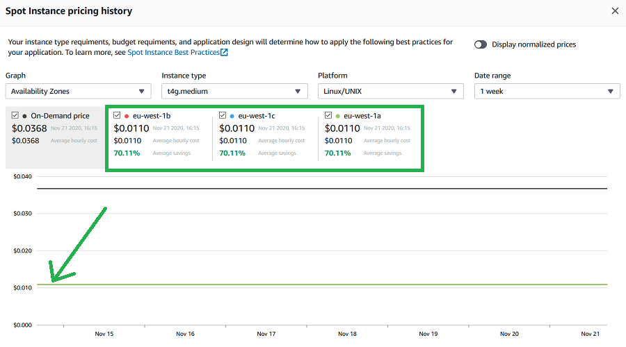
If you don’t need 4GB of RAM, you can drop down to a t4g.small instance type for half the cost.

Total monthly running costs should be around $8.91.

Keep in mind that this solution will provide multiple hostname support (multiple domains/sites hosted on the same system), storage persistence, and a pretty quick and responsive ARM based Graviton2 processor.

You will need to use ARM compatible Docker images, but there are plenty out there for all the standard software like MySQL, WordPress, Adminer, etc…

How it Works

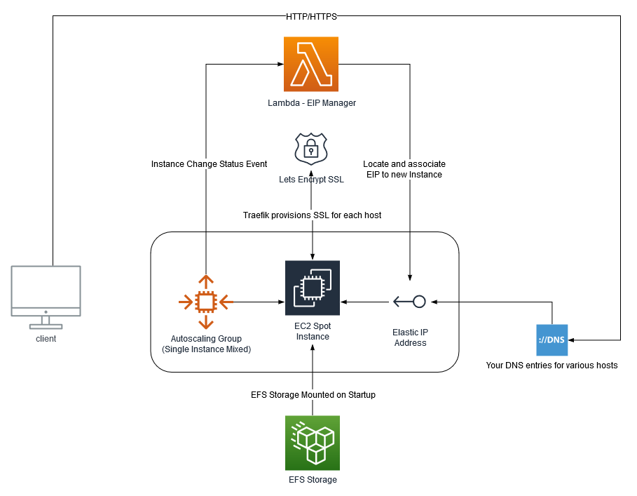
The infrastructure diagram above pretty much explains how everything fits together. But at a high level:

  • An Autoscaling Group is created, in mixed mode, but only allows a single, spot instance. This EC2 instance uses a standard Amazon Linux 2 ARM based AMI (machine image).
  • When the new instance is created, a Lambda function (subscribed to EC2 lifecycle events) is invoked, locates a designated Elastic IP (EIP), and associates it with the new spot EC2 instance.
  • The EC2 machine mounts the EFS storage on startup, and bootstraps itself with software requirements, a base Traefik configuration, as well as your custom ‘dynamic’ Traefik configuration that you specify. It then launches the Traefik container.
  • You point your various A records in DNS to the public IP address of the EIP.
  • Now it doesn’t matter if your EC2 spot instance is terminated, you’ll always have the same IP address, and the same EFS storage mounted when the new one starts up.
  • There is the question of ‘what if the spot market goes haywire?’ By default the spot price will be allowed to go all the way up to the on-demand price. This means you could potentially pay more for the EC2 instance, but it is not likely. If it did happen, you could change the instance configuration or choose another instance type.

Deploying the Solution

As this is an AWS opinionated infrastructure choice, I’ve packaged everything into an AWS Cloud Development Kit (AWS CDK) app. AWS CDK is an open source software development framework that allows you to do infrastructure-as-code. I’ve used Typescript as my language of choice.

Clone the source from GitHub

Deploy Requirements

You’ll need the following requirements on your local machine to deploy this for yourself:

  • NodeJS installed, along with npm.
  • AWS CDK installed globally (npm install -g aws-cdk)
  • Define your own traefik_dynamic.toml configuration, and host it somewhere where the EC2 instance will be able to grab it with curl. Note, that the Traefik dashboard basic auth password is defined using htpasswd.
htpasswd -nb YourUsername YourSuperSecurePasswordGoesHere
  • An existing VPC in your account to use. The CDK app does not create a VPC (additional cost). You can definitely use your default account VPC that is already available in all accounts though.
  • An existing AWS Keypair
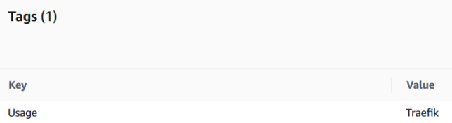
  • An existing Elastic IP address (EIP) created, and tagged with the key/value of Usage:Traefik (this is for the Lambda function to identify the right EIP to associate to the EC2 instance when it starts)
Tag requirement for the Elastic IP Address

I haven’t set up the CDK app to pass in parameters, so you’ll just need to modify a bunch of variables at the top of aws-docker-web-with-traefik-stack.ts to substitute your specific values for the aforementioned items. For example:

const vpcId = "your-vpc-id";
const instanceType = "t4g.medium"; // t4g.small for even more cost saving
const keypairName = "your-existing-keypair-name";
const managementLocationCidr = "1.1.1.1/32"; // your home / management network address that SSH access will be allowed from. Change this!
const traefikDynContentUrl = "https://gist.githubusercontent.com/Shogan/f96a5a20183e672f9c49f278ea67503b/raw/351c52b7f2bacbf7b8dae65404b61ff4e4313d81/example-traefik-dynamic.toml"; // this should point to your own dynamic traefik config in toml format.
const emailForLetsEncryptAcmeResolver = 'email = "youremail@example.com"'; // update this to your own email address for lets encrypt certs
const efsAutomaticBackups = false; // set to true to enable automatic backups for EFS

Build and Deploy

Build the Typescript project using npm run build. This compiles the CDK and the EIP Manager Lambda function typescript.

At this point you’re ready to deploy with CDK.

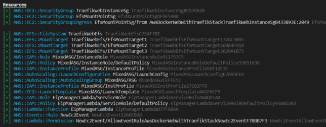
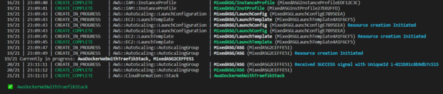
If you have not used CDK before, all you really need to know is that it takes the infrastructure described by the code (typescript in this case), and coverts it to CloudFormation language. The cdk deploy command deploys the stack (which is the collection of AWS resources defined in code).

Run:

# Check what changes will be made first
cdk diff

# Deploy
cdk deploy

Testing a Sample Application Stack

Here is a sample docker-compose stack that will install MySQL, Adminer, and a simple WordPress setup.

SSH onto the EC2 instance that is provisioned, and use docker-compose up -d deploy the compose example stack. Just remember to edit and change the template passwords in the two environment variables.

You’ll also need to update the hostnames to your own (from .example.com), and point those A records to your Elastic public IP address.

One more thing, there is a trick to running docker-compose on ARM systems. I personally prefer to grab a docker image that contains a pre-built docker-compose binary, and shell script that ties it together with the docker-compose command. Here are the steps if you need them (run on the EC2 instance that you SSH onto):

sudo curl -L --fail https://raw.githubusercontent.com/linuxserver/docker-docker-compose/master/run.sh -o /usr/local/bin/docker-compose
sudo chmod +x /usr/local/bin/docker-compose

For your own peace of mind, make sure you inspect that githubusercontent run.sh script yourself before downloading, as well as the docker image(s) it references and pulls down to run docker-compose.

Tear Down

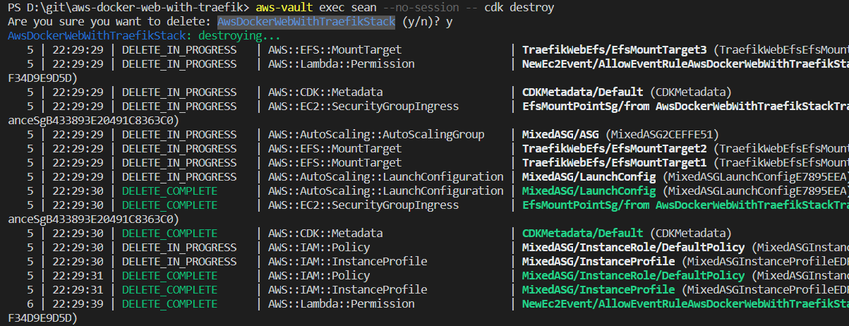
To destroy the stack, simply issue the cdk destroy command. The EFS storage is marked by default with a retain policy, so it will not be deleted automatically.

cdk destroy AwsDockerWebWithTraefikStack
deleting the minimal cost web hosting solution cdk stack

Closing

If you’re on the look out for a minimal cost web hosting solution, then give this a try.

The stack uses the new Graviton2 based t4g instance type (ARM) to help achieve a minimal cost web hosting setup. Remember to find compatible ARM docker images for your applications before you go all in with something like this.

The t4g instance family is also a ‘burstable’ type. This means you’ll get great performance as long as you don’t use up your burst credits. Performance will slow right down if that happens. Keep an eye on your burst credit balance with CloudWatch. For 99% of use cases you’ll likely be just fine though.

Also remember that you don’t need to stick to AWS. You could bolt together services from any other cloud provider to do something similiar, most likely at a similar cost too.

Hashicorp Waypoint Server on Raspberry Pi

waypoint server running on raspberry pi

This evening I finally got a little time to play around with Waypoint. This wasn’t a straightforward install of Waypoint on my desktop though. I wanted to run and test HashiCorp Waypoint Server on Raspberry Pi. Specifically on my Pi Kubernetes cluster.

Out of the box Waypoint is simple to setup locally, whether you’re on Windows, Linux, or Mac. The binary is written in the Go programming language, which is common across HashiCorp software.

There is even an ARM binary available which lets you run the CLI on Raspberry Pi straight out of the box.

Installing Hashicorp Waypoint Server on Raspberry Pi hosted Kubernetes

I ran into some issues initially when assuming that waypoint install --platform=kubernetes -accept-tos would ensure an ARM docker image was pulled down for my Pi based Kubernetes hosts though.

My Kubernetes cluster also has the nfs-client-provisioner setup, which fulfills PersistentVolumeClaim resources with storage from my home FreeNAS Server Build. I noticed that PVCs were not being honored because they did not have the specific storage-class of nfs-storage that my nfs-client-provisioner required.

Fixing the PVC Issue

Looking at the waypoint CLI command, it’s possible to generate the YAML for the Kubernetes resources it would deploy with a --platform=kubernetes flag. So I fetched a base YAML resource definition:

waypoint install --platform=kubernetes -accept-tos --show-yaml

I modified the volumeClaimTemplates section to include my required PVC storageClassName of nfs-storage.

volumeClaimTemplates:
  - metadata:
      name: data
    spec:
      accessModes: [ "ReadWriteOnce" ]
      storageClassName: nfs-storage
      resources:
        requests:
          storage: 1Gi

That sorted out the pending PVC issue in my cluster.

Fixing the ARM Docker Issue

Looking at the Docker image that the waypoint install command for Kubernetes gave me, I could see right away that it was not right for ARM architecture.

To get a basic Waypoint server deployment for development and testing purposes on my Raspberry Pi Kubernetes Cluster, I created a simple Dockerfile for armhf builds.

Basing it on the hypriot/rpi-alpine image, to get things moving quickly I did the following in my Dockerfile.

  • Added few tools, such as cURL.
  • Added a RUN command to download the waypoint ARM binary (currently 0.1.3) from Hashicorp releases and place in /usr/bin/waypoint.
  • Setup a /data volume mount point.
  • Created a waypoint user.
  • Created the entrypoint for /usr/bin/waypoint.

You can get my ARM Waypoint Server Dockerfile on Github, and find the built armhf Docker image on Docker Hub.

Now it is just a simple case of updating the image in the generated YAML StatefulSet to use the ARM image with the ARM waypoint binary embedded.

containers:
- name: server
  image: shoganator/waypoint:0.1.3.20201026-armhf
  imagePullPolicy: Always

With the YAML updated, I simply ran kubectl apply to deploy it to my Kubernetes Cluster. i.e.

kubectl apply -f ./waypoint-armhf.yaml

Now Waypoint Server was up and running on my Raspberry Pi cluster. It just needed bootstrapping, which is expected for a new installation.

Hashicorp Waypoint Server on Raspberry Pi - pod started.

Configuring Waypoint CLI to Connect to the Server

Next I needed to configure my internal jumpbox to connect to Waypoint Server to verify everything worked.

Things may differ for you here slightly, depending on how your cluster is setup.

Waypoint on Kubernetes creates a LoadBalancer resource. I’m using MetalLB in my cluster, so I get a virtual LoadBalancer, and the EXTERNAL-IP MetalLB assigned to the waypoint service for me was 10.23.220.90.

My cluster is running on it’s own dedicated network in my house. I use another Pi as a router / jumpbox. It has two network interfaces, and the internal interface is on the Kubernetes network.

By getting an SSH session to this Pi, I could verify the Waypoint Server connectivity via it’s LoadBalancer resource.

curl -i --insecure https://10.23.220.90:9702

HTTP/1.1 200 OK
Accept-Ranges: bytes
Content-Length: 3490
Content-Type: text/html; charset=utf-8
Last-Modified: Mon, 19 Oct 2020 21:11:45 GMT
Date: Mon, 26 Oct 2020 14:27:33 GMT

Bootstrapping Waypoint Server

On a first time run, you need to bootstrap Waypoint. This also sets up a new context for you on the machine you run the command from.

The Waypoint LoadBalancer has two ports exposed. 9702 for HTTPS, and 9701 for the Waypoint CLI to communicate with using TCP.

With connectivity verified using curl, I could now bootstrap the server with the waypoint bootstrap command, pointing to the LoadBalancer EXTERNAL-IP and port 9701.

waypoint server bootstrap -server-addr=10.23.220.90:9701 -server-tls-skip-verify
waypoint context list
waypoint context verify

This command gives back a token as a response and sets up a waypoint CLI context from the machine it ran from.

Waypoint context setup and verified from an internal kubernetes network connected machine.

Using Waypoint CLI from a machine external to the Cluster

I wanted to use Waypoint from a management or workstation machine outside of my Pi Cluster network. If you have a similar network setup, you could also do something similar.

As mentioned before, my Pi Router device has two interfaces. A wireless interface, and a phyiscal network interface. To get connectivity over ports 9701 and 9702 I used some iptables rules. Importantly, my Kubernetes facing network interface is on 10.0.0.1 in the example below:

sudo iptables -t nat -A PREROUTING -i wlan0 -p tcp --dport 9702 -j DNAT --to-destination 10.23.220.90:9702
sudo iptables -t nat -A POSTROUTING -p tcp -d 10.23.220.90 --dport 9702 -j SNAT --to-source 10.0.0.1
sudo iptables -t nat -A PREROUTING -i wlan0 -p tcp --dport 9701 -j DNAT --to-destination 10.23.220.90:9701
sudo iptables -t nat -A POSTROUTING -p tcp -d 10.23.220.90 --dport 9701 -j SNAT --to-source 10.0.0.1

These rules have the effect of sending traffic destined for port 9701 and 9702 hitting the wlan0 interface, to the MetalLB IP 10.23.220.90.

The source and destination network address translation will translate the ‘from’ address of the TCP reply packets to make them look like they’re coming from 10.0.0.1 instead of 10.23.220.90.

Now, I can simply setup a Waypoint CLI context on a machine on my ‘normal’ network. This network has visibility of my Raspberry Pi Router’s wlan0 interface. I used my previously generated token in the command below:

waypoint context create -server-addr=192.168.7.31:9701 -server-tls-skip-verify -server-auth-token={generated-token-here} rpi-cluster
waypoint context verify rpi-cluster
Connectivity verified from my macOS machine, external to my Raspberry Pi Cluster with Waypoint Server running there.

Concluding

Waypoint Server is super easy to get running locally if you’re on macOS, Linux or Windows.

With a little bit of extra work you can get HashiCorp Waypoint Server on Raspberry Pi working, thanks to the versatility of the Waypoint CLI!

Raspberry Pi Kubernetes Cluster with OpenFaaS for Serverless Functions (Part 4)

Getting Started with OpenFaaS

This is the fourth post in this series. The focus will be on getting OpenFaaS set up on your Raspberry Pi Kubernetes cluster nice and quickly.

Here are some links to previous posts in this series:

OpenFaaS is an open source project that provides a scalable platform to easily deploy event-driven functions and microservices.

It has great support to run on ARM hardware, which makes it an excellent fit for the Raspberry Pi. It’s worth mentioning that it is of course designed to run across a multitude of different platforms other than the Pi.

Getting Started

You’ll work with a couple of different CLI tools that I chose for the speed at which they can get you up and running:

  • faas-cli – the main CLI for OpenFaaS
  • arkade – a golang based CLI tool for quick and easy one liner installs for various apps / software for Kubernetes

There are other options like Helm or standard YAML files for Kubernetes that you could also use. Find more information about these here.

I have a general purpose admin and routing dedicated Pi in my Raspberry Pi stack that I use for doing admin tasks in my cluster. This made for a great bastion host that I could use to run the following commands:

Install arkade

# Important! Before running these scripts, always inspect the remote content first, especially as they're piped into sh with 'sudo'

# MacOS or Linux
curl -SLsf https://dl.get-arkade.dev/ | sudo sh

# Windows using Bash (e.g. WSL or Git Bash)
curl -SLsf https://dl.get-arkade.dev/ | sh

Install faas-cli

# Important! Before running these scripts, always inspect the remote content first, especially as they're piped into sh with 'sudo'

# MacOS
brew install faas-cli

# Using curl
curl -sL https://cli.openfaas.com | sudo sh

Deploying OpenFaaS

Using arkade, deploy OpenFaaS with:

arkade install openfaas

If you followed my previous articles in this series to set your cluster up, then you’ll have a LoadBalancer service type available via MetalLB. However, in my case (with the above command), I did not deploy a LoadBalancer service, as I already use a single Ingress Controller for external traffic coming into my cluster.

The assumption is that you have an Ingress Controller setup for the remainder of the steps. However, you can get by without one, accessing OpenFaaS by the external gateway NodePortservice instead.

The arkade install will output a command to get your password. By default OpenFaaS comes with Basic Authentication. You’ll fetch the admin password you can use to access the system with Basic Auth next.

Grab the generated admin password and login with faas-cli:

PASSWORD=$(kubectl get secret -n openfaas basic-auth -o jsonpath="{.data.basic-auth-password}" | base64 --decode; echo)
echo -n $PASSWORD | faas-cli login --username admin --password-stdin

OpenFaaS Gateway Ingress

OpenFaaS will have deployed with two Gateway services in the openfaas namespace.

  • gateway (ClusterIP)
  • gateway-external (NodePort)

Instead of relying on the NodePort service, I chose to create an Ingress Rule to send traffic from my cluster’s Ingress Controller to OpenFaaS’ ClusterIP service (gateway).

You’ll want SSL so setup a K8s secret to hold your certificate details for the hostname you choose for your Ingress Rule. Here is a template you can use for your OpenFaaS ingress:

apiVersion: extensions/v1beta1
kind: Ingress
metadata:
  annotations:
    kubernetes.io/ingress.class: nginx
    nginx.ingress.kubernetes.io/rewrite-target: /
  name: openfaas
spec:
  rules:
  - host: openfaas.foo.bar
    http:
      paths:
      - backend:
          serviceName: gateway
          servicePort: 8080
        path: /
  tls:
  - hosts:
    - openfaas.foo.bar
    secretName: openfaas.foo.bar

Create your TLS K8s secret in the openfaas namespace, and then deploy the ingress rule with:

kubectl -n openfaas apply -f ./the_above_ingress_rule.yml

You should now be able to access the OpenFaaS UI with something like https://openfaas.foo.bar/ui/

The OpenFaas Web UI

Creating your own Functions

Life is far more fun on the CLI, so get started with some basics with first:

  • faas-cli store list --platform armhf – show some basic functions available for armhf (Pi)
  • faas-cli store deploy figlet --platform armhf – deploy the figlet function that converts text to ASCII representations of that text
  • echo "hai" | faas-cli invoke figlet – pipe the text ‘hai’ into the faas-cli invoke command to invoke the figlet function and get it to generate the equivalent in ASCII text.

Now, create your own function using one of the many templates available. You’ll be using the incubator template for python3 HTTP. This includes a newer function watchdog (more about that below), which gives more control over the HTTP / event lifecycle in your functions.

Grab the python3 HTTP template for armhf and create a new function with it:

# Grab incubator templates for Python, including Python HTTP. Will figure out it needs the armhf ones based on your architecture!

faas template pull https://github.com/openfaas-incubator/python-flask-template
faas-cli new --lang python3-http-armhf your-function-name-here
Success – a new, python3 HTTP function ready to go

A basic file structure gets scaffolded out. It contains a YAML file with configuration about your function. E.g.

version: 1.0
provider:
  name: openfaas
  gateway: http://127.0.0.1:8080
functions:
  your-function-name-here:
    lang: python3-http-armhf
    handler: ./your-function-name-here
    image: your-function-name-here:latest

The YAML informs building and deploying of your function.

A folder with your function handler code is also created alongside the YAML. For python it contains handler.py and requirements.txt (for python library requirements)

def handle(event, context):
    # TODO implement
    return {
        "statusCode": 200,
        "body": "Hello from OpenFaaS!"
    }

As you used the newer function templates with the latest OF Watchdog, you get full access to the event and context in your handler without any extra work. Nice!

Build and Deploy your Custom Function

Run the faas up command to build and publish your function. This will do a docker build / tag / push to a registry of your choice and then deploy the function to OpenFaaS. Update your your-function-name-here.yml file to specify your desired docker registry/repo/tag, and OpenFaas gateway address first though.

faas up -f your-function-name-here.yml

Now you’re good to go. Execute your function by doing a GET request to the function URL, using faas invoke, or by using the OpenFaaS UI!

Creating your own OpenFaaS Docker images

You can convert most Docker images to run on OpenFaaS by adding the function watchdog to your image. This is a very small HTTP server written in Golang.

It becomes the entrypoint which forwards HTTP requests to your target process via STDIN or HTTP. The response goes back to the requester by STDOUT or HTTP.

Read and find out more at these URLs:

Hopefully this gave you a good base to get started with OpenFaaS. We covered everything from deployment and configuration, to creating your own custom functions and images. Have fun experimenting!

Building a Pi Kubernetes Cluster – Part 3 – Worker Nodes and MetalLB

Building a Raspberry Pi Kubernetes Cluster - part 3 - worker nodes featured image

This is the third post in this series and the focus will be on completing the Raspberry Pi Kubernetes cluster by adding a worker node. You’ll also setup a software based load-balancer implementation designed for bare metal Kubernetes Clusters by leveraging MetalLB.

Here are some handy links to other parts in this blog post series:

By now you should have 1 x Pi running as the dedicated Pi network router, DHCP, DNS and jumpbox, as well as 1 x Pi running as the cluster Master Node.

Of course it’s always best to have more than 1 x Master node, but as this is just an experimental/fun setup, one is just fine. The same applies to the Worker nodes, although in my case I added two workers with each Pi 4 having 4GB RAM.

Joining a Worker Node to the Cluster

Start off by completing the setup steps as per the Common Setup section in Part 2 with your new Pi.

Once your new Worker Pi is ready and on the network with it’s own static DHCP lease, join it to the cluster (currently only the Master Node) by using the kubeadm join command you noted down when you first initialised your cluster in Part 2.

E.g.

sudo kubeadm join 10.0.0.50:6443 --token kjx8lp.wfr7n4ie33r7dqx2 \
     --discovery-token-ca-cert-hash sha256:25a997a1b37fb34ed70ff4889ced6b91aefbee6fb18e1a32f8b4c8240db01ec3

After a few moments, SSH back to your master node and run kubectl get nodes. You should see the new worker node added and after it pulls down and starts the weave net CNI image it’s status will change to Ready.

kubernetes worker node added to cluster

Setting up MetalLB

The problem with a ‘bare metal’ Kubernetes cluster (or any self-installed, manually configured k8s cluster for that matter) is that it doesn’t have any load-balancer implementation to handle LoadBalancer service types.

When you run Kubernetes on top of a cloud hosting platform like AWS or Azure, they are backed natively by load-balancer implementations that work seamlessly with those cloud platform’s load-balancer services. E.g. classic application or elastic load balancers with AWS.

However, with a Raspberry Pi cluster, you don’t have anything fancy like that to provide LoadBalancer services for your applications you run.

MetalLB provides a software based implementation that can work on a Pi cluster.

Install version 0.8.3 of MetalLB by applying the following manifest with kubectl:

kubectl apply -f https://gist.githubusercontent.com/Shogan/d418190a950a1d6788f9b168216f6fe1/raw/ca4418c7167a64c77511ba44b2c7736b56bdad48/metallb.yaml

Make sure the MetalLB pods are now up and running in the metallb-system namespace that was created.

metallb pods running

Now you will create a ConfigMap that will contain the settings your MetalLB setup will use for the cluster load-balancer services.

Create a file called metallb-config.yaml with the following content:

apiVersion: v1
kind: ConfigMap
metadata:
  namespace: metallb-system
  name: config
data:
  config: |
    address-pools:
    - name: default
      protocol: layer2
      addresses:
      - 10.23.220.88-10.23.220.98

Update the addresses section to use whichever range of IP addresses you would like to assign for use with MetalLB. Note, I only used 10 addresses as below for mine.

Apply the configuration:

kubectl apply -f ./metallb-config.yaml

Setup Helm in the Pi Cluster

First of all you’ll need an ARM compatible version of Helm. Download it and move it to a directory that is in your system PATH. I’m using my Kubernetes master node as a convenient location to use kubectl and helm commands from, so I did this on my master node.

Install Helm Client

export HELM_VERSION=v2.9.1
wget https://kubernetes-helm.storage.googleapis.com/helm-$HELM_VERSION-linux-arm.tar.gz
tar xvzf helm-$HELM_VERSION-linux-arm.tar.gz
sudo mv linux-arm/helm /usr/bin/helm

Install Helm Tiller in the Cluster

Use the following command to initialise the tiller component in your Pi cluster.

helm init --tiller-image=jessestuart/tiller --service-account tiller --override spec.selector.matchLabels.'name'='tiller',spec.selector.matchLabels.'app'='helm' --output yaml | sed 's@apiVersion: extensions/v1beta1@apiVersion: apps/v1@' | kubectl apply -f -

Note: it uses a custom image from jessestuart/tiller (as this is ARM compatible). The command also replaces the older api spec for the deployment with the apps/v1 version, as the older beta one is no longer applicable with Kubernetes 1.16.

Deploy an Ingress Controller with Helm

Now that you have something to fulfill LoadBalancer service types (MetalLB), and you have Helm configured, you can deploy an NGINX Ingress Controller with a LoadBalancer service type for your Pi cluster.

helm install --name nginx-ingress stable/nginx-ingress --set rbac.create=true --set controller.service.type=LoadBalancer

If you list out your new ingress controller pods though you might find a problem with them running. They’ll likely be trying to use x86 architecture images instead of ARM. I manually patched my NGINX Ingress Controller deployment to point it at an ARM compatible docker image.

kubectl set image deployment/nginx-ingress-controller     nginx-ingress-controller=quay.io/kubernetes-ingress-controller/nginx-ingress-controller-arm:0.26.1

After a few moments the new pods should now show as running:

new nginx ingress pods running with ARM image

Now to test everything, you can grab the external IP that should have been assigned to your NGINX ingress controller LoadBalancer service and test the default NGINX backend HTTP endpoint that returns a simple 404 message.

List the service and get the EXTERNAL-IP (this should sit in the range you configured MetalLB with):

kubectl get service --selector=app=nginx-ingress

Curl the NGINX Ingress Controller LoadBalancer service endpoint with a simple GET request:

curl -i http://10.23.220.88

You’ll see the default 404 not found response which indicates that the controller did indeed receive your request from the LoadBalancer service and directed it appropriately down to the default backend pod.

the nginx default backend 404 response

Concluding

At this point you’ve configured:

  • A Raspberry Pi Kubernetes network Router / DHCP / DNS server / jumpbox
  • Kubernetes master node running the master components for the cluster
  • Kubernetes worker nodes
  • MetalLB load-balancer implementation for your cluster
  • Helm client and Tiller agent for ARM in your cluster
  • NGINX ingress controller

In part 1, recall you setup some iptables rules on the Router Pi as an optional step?

These PREROUTING AND POSTROUTING rules were to forward packets destined for the Router Pi’s external IP address to be forwarded to a specific IP address in the Kubernetes network. In actual fact, the example I provided was what I used to forward traffic from the Pi router all the way to my NGINX Ingress Controller load balancer service.

Revisit this section if you’d like to achieve something similar (access services inside your cluster from outside the network), and replace the 10.23.220.88 IP address in the example I provided with the IP address of your own ingress controller service backed by MetalLB in your cluster.

Also remember that at this point you can add as many worker nodes to the cluster as you like using the kubeadm join command used earlier.