Saga Pattern with aws-cdk, Lambda, and Step Functions

steps

The saga pattern is useful when you have transactions that require a bunch of steps to complete successfully, with failure of steps requiring associated rollback processes to run. This post will cover the saga pattern with aws-cdk, leveraging AWS Step Functions and Lambda.

If you need an introduction to the saga pattern in an easy to understand format, I found this GOTO conference session by Caitie McCaffrey very informative.

Another useful resource with regard to the saga pattern and AWS Step Functions is this post over at theburningmonk.com.

Saga Pattern with aws-cdk

I’ll be taking things one step further by automating the setup and deployment of a sample app which uses the saga pattern with aws-cdk.

I’ve started using aws-cdk fairly frequently, but realise it has the issue of vendor lock-in. I found it nice to work with in the case of step functions particularly in the way you construct step chains.

Saga Pattern with Step Functions

So here is the step function state machine you’ll create using the fairly simple saga pattern aws-cdk app I’ve set up.

saga pattern with aws-cdk - a successful transaction run
A successful transaction run

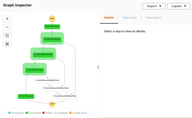
Above you see a successful transaction run, where all records are saved to a DynamoDB table entry.

dynamodb data from sample app using saga pattern with aws-cdk
The sample data written by a succesful transaction run. Each step has a ‘Sample’ map entry with ‘Data’ and a timestamp.

If one of those steps were to fail, you need to manage the rollback process of your transaction from that step backwards.

Illustrating Failure Rollback

As mentioned above, with the saga pattern you’ll want to rollback any steps that have run from the point of failure backward.

The example app has three steps:

  • Process Records
  • Transform Records
  • Commit Records

Each step is a simple lambda function that writes some data to a DynamoDB table with a primary partition key of TransactionId.

In the screenshot below, TransformRecords has a simulated failure, which causes the lambda function to throw an error.

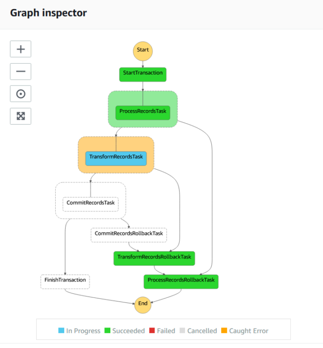
A catch step is linked to each of the process steps to handle rollback for each of them. Above, TransformRecordsRollbackTask is run when TransformRecordsTask fails.

The rollback steps cascade backward to the first ‘business logic’ step ProcessRecordsTask. Any steps that have run up to that point will therefore have their associated rollback tasks run.

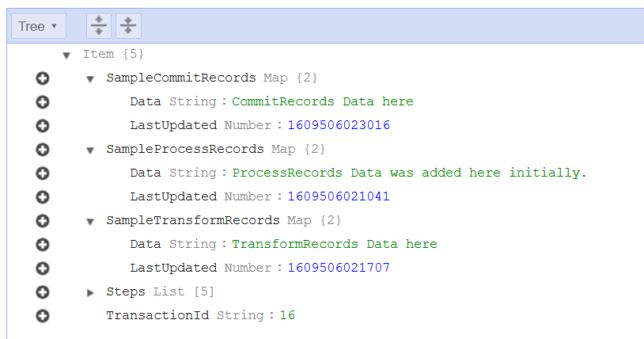
Here is what an entry looks like in DynamoDB if it failed:

A failed transaction has no written data, because the data written up to the point of failure was ‘rolled back’.

You’ll notice this one does not have the ‘Sample’ data that you see in the previously shown successful transaction. In reality, for a brief moment it does have that sample data. As each rollback step is run, the associated data for that step is removed from the table entry, resulting in the above entry for TransactionId 18.

Deploying the Sample Saga Pattern App with aws-cdk

Clone the source code for the saga pattern aws-cdk app here.

You’ll need to npm install and typescript compile first. From the root of the project:

npm install && npm run build

Now you can deploy using aws-cdk.

# Check what you'll deploy / modify first with a diff
cdk diff
# Deploy
cdk deploy

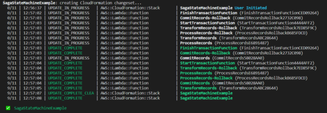
With the stack deployed, you’ll now have the following resources:

  • Step Function / State Machine
  • Various Lambda functions for transaction start, finish, the process steps, and each process rollback step.
  • A DynamoDB table for the data
  • IAM role(s) created for the above

Testing the Saga Pattern Sample App

To test, head over to the Step Functions AWS Console and navigate to the newly created SagaStateMachineExample state machine.

Click New Execution, and paste the following for the input:

{
    "Payload": {
      "TransactionDetails": {
        "TransactionId": "1"
      }
    }
}

Click Start Execution.

In a few short moments, you should have a successful execution and you should see your transaction and sample data in DynamoDB.

Moving on, to simulate a random failure, try executing again, but this time with the following payload:

{
    "Payload": {
      "TransactionDetails": {
        "TransactionId": "2",
        "simulateFail": true
      }
    }
}

The lambda functions check the payload input for the simulateFail flag, and if found will do a Math.random() check to give chance of failure in one of the process steps.

Taking it Further

To take this example further, you’ll want to more carefully manage step outputs using Step Function ResultPath configuration. This will ensure that your steps don’t overwrite data in the state machine and that steps further down the line have access to the data that they need.

You’ll probably also want a step at the end of the line for the case of failure (which runs after all rollback steps have completed). This can handle notifications or other tasks that should run if a transaction fails.

AWS CodeBuild local with Docker

AWS have a handy post up that shows you how to get CodeBuild local by running it with Docker here.

Having a local CodeBuild environment available can be extremely useful. You can very quickly test your buildspec.yml files and build pipelines without having to go as far as push changes up to a remote repository or incurring AWS charges by running pipelines in the cloud.

I found a few extra useful bits and pieces whilst running a local CodeBuild setup myself and thought I would document them here, along with a summarised list of steps to get CodeBuild running locally yourself.

Get CodeBuild running locally

Start by cloning the CodeBuild Docker git repository.

git clone https://github.com/aws/aws-codebuild-docker-images.git

Now, locate the Dockerfile for the CodeBuild image you are interested in using. I wanted to use the ubuntu standard 3.0 image. i.e. ubuntu/standard/3.0/Dockerfile.

Edit the Dockerfile to remove the ENTRYPOINT directive at the end.

# Remove this -> ENTRYPOINT ["dockerd-entrypoint.sh"]

Now run a docker build in the relevant directory.

docker build -t aws/codebuild/standard:3.0 .

The image will take a while to build and once done will of course be available to run locally.

Now grab a copy of this codebuild_build.sh script and make it executable.

curl -O https://gist.githubusercontent.com/Shogan/05b38bce21941fd3a4eaf48a691e42af/raw/da96f71dc717eea8ba0b2ad6f97600ee93cc84e9/codebuild_build.sh
chmod +x ./codebuild_build.sh

Place the shell script in your local project directory (alongside your buildspec.yml file).

Now it’s as easy as running this shell script with a few parameters to get your build going locally. Just use the -i option to specify the local docker CodeBuild image you want to run.

./codebuild_build.sh -c -i aws/codebuild/standard:3.0 -a output

The following two options are the ones I found most useful:

  • -c – passes in AWS configuration and credentials from the local host. Super useful if your buildspec.yml needs access to your AWS resources (most likely it will).
  • -b – use a buildspec.yml file elsewhere. By default the script will look for buildspec.yml in the current directory. Override with this option.
  • -e – specify a file to use as environment variable mappings to pass in.

Testing it out

Here is a really simple buildspec.yml if you want to test this out quickly and don’t have your own handy. Save the below YAML as simple-buildspec.yml.

version: 0.2

phases:
  install:
    runtime-versions:
      java: openjdk11
    commands:
      - echo This is a test.
  pre_build:
    commands:
      - echo This is the pre_build step
  build:
    commands:
      - echo This is the build step
  post_build:
    commands:
      - bash -c "if [ /"$CODEBUILD_BUILD_SUCCEEDING/" == /"0/" ]; then exit 1; fi"
      - echo This is the post_build step
artifacts:
  files:
    - '**/*'
  base-directory: './'

Now just run:

./codebuild_build.sh -b simple-buildspec.yml -c -i aws/codebuild/standard:3.0 -a output /tmp

You should see the script start up the docker container from your local image and ‘CodeBuild’ will start executing your buildspec steps. If all goes well you’ll get an exit code of 0 at the end.

aws codebuild test run output from a local Docker container.

Good job!

This post contributes to my effort towards 100DaysToOffload.

Saving £500 on a new Apple Mac Mini with 32GB RAM

mac mini internals

I purchased a new Apple Mac Mini recently and didn’t want to fall victim to Apple’s “RAM Tax”.

I used Apple’s site to configure a Mac Mini with a quad core processor, 32GB RAM, and a 512GB SSD.

I was shocked to see they added £600.00 to the price of a base model with 8GB RAM. They’re effectively charging all of this money for 24GB of extra RAM. This memory is nothing special, it’s pretty standard 2666MHz DDR4 SODIMM modules. The same stuff that is used in generic laptops.

I decided to cut back my order to the base model with 8GB of RAM. I ordered a Crucial 32GB Kit (2 x 16GB DDR4-2666 SODIMM modules running at 1.2 volts with a CAS latency of 19ns). This kit cost me just over £100.00 online.

The Crucial 2 x 16GB DDR4-2666 SODIMM kit

In total I saved around £500.00 for the trouble of about 30 minutes of work to open up the Mac Mini and replace the RAM modules myself.

The Teardown Process

Use the iFixit Guide

You can use my photos and brief explanations below if you would like to follow the steps I took to replace the RAM, but honestly, you’re better off following iFixit’s excellent guide here.

Follow along Here

If you want to compare or follow along in my format, then read on…

Get a good tool kit with hex screw drivers. I used iFixit’s basic kit.

iFixit basic tool kit

Flip the Mac Mini upside down.

Pry open the back cover, carefully with a plastic prying tool

Undo the 6 x hex screws on the metal plate under the black plastic cover. Be careful to remember the positions of these, as there are 2 x different types. 3 x short screws, and 3 x longer.

opening the mac mini

Very carefully, move the cover to the side, revealing the WiFi antenna connector. Unscrew the small hex screw holding the metal tab on the cable. Use a plastic levering tool to carefully pop the antenna connector off.

Next, unscrew 4 x screws that hold the blower fan to the exhaust port. You can see one of the screws in the photo below. Two of the screws are angled at a 45 degree orientation, so carefully undo those, and use tweezers to catch them as they come out.

Carefully lift the blower fan up, and disconnect it’s cable using a plastic pick or prying tool. The trick is to lift from underneat the back of the cable’s connector and it’ll pop off.

mac mini blower fan removal

Next, disconnect the main power cable at the top right of the photo below. This requires a little bit of wiggling to loosen and lift it as evenly as possible.

Now disconnect the LED cable (two pin). It’s very delicate, so do this as carefully as possible.

There are two main hex screws to remove from the motherboard central area now. You can see them removed below near the middle (where the brass/gold coloured rings are).

With everything disconnected, carefully push the inner motherboard and it’s tray out, using your thumbs on the fan’s exhaust port. You should ideally position your thumbs on the screw hole areas of the fan exhaust port. It’ll pop out, then just very carefully push it all the way out.

The RAM area is protected by a metal ‘cage’. Unscrew it’s 4 x hex screws and slowly lift the cage off the RAM retainer clips.

Carefully push the RAM module retainer clips to the side (they have a rubber grommet type covering over them), and the existing SODIMM modules will pop loose.

mac mini SODIMM RAM modules and slots

Remove the old modules and replace with your new ones. Make sure you align the modules in the correct orientation. The slots are keyed, so pay attention to that. Push them down toward the board once aligned and the retainer clips will snap shut and lock them in place.

Replace the RAM ‘cage’ with it’s 4 x hex screws.

Reverse the steps you took above to insert the motherboard tray back into the chassis and re-attach all the cables and connectors in the correct order.

Make sure you didn’t miss any screws or cables when reconnecting everything.

Finally boot up and enjoy your cheap RAM upgrade.

Raspberry Pi Kubernetes Cluster with OpenFaaS for Serverless Functions (Part 4)

Getting Started with OpenFaaS

This is the fourth post in this series. The focus will be on getting OpenFaaS set up on your Raspberry Pi Kubernetes cluster nice and quickly.

Here are some links to previous posts in this series:

OpenFaaS is an open source project that provides a scalable platform to easily deploy event-driven functions and microservices.

It has great support to run on ARM hardware, which makes it an excellent fit for the Raspberry Pi. It’s worth mentioning that it is of course designed to run across a multitude of different platforms other than the Pi.

Getting Started

You’ll work with a couple of different CLI tools that I chose for the speed at which they can get you up and running:

  • faas-cli – the main CLI for OpenFaaS
  • arkade – a golang based CLI tool for quick and easy one liner installs for various apps / software for Kubernetes

There are other options like Helm or standard YAML files for Kubernetes that you could also use. Find more information about these here.

I have a general purpose admin and routing dedicated Pi in my Raspberry Pi stack that I use for doing admin tasks in my cluster. This made for a great bastion host that I could use to run the following commands:

Install arkade

# Important! Before running these scripts, always inspect the remote content first, especially as they're piped into sh with 'sudo'

# MacOS or Linux
curl -SLsf https://dl.get-arkade.dev/ | sudo sh

# Windows using Bash (e.g. WSL or Git Bash)
curl -SLsf https://dl.get-arkade.dev/ | sh

Install faas-cli

# Important! Before running these scripts, always inspect the remote content first, especially as they're piped into sh with 'sudo'

# MacOS
brew install faas-cli

# Using curl
curl -sL https://cli.openfaas.com | sudo sh

Deploying OpenFaaS

Using arkade, deploy OpenFaaS with:

arkade install openfaas

If you followed my previous articles in this series to set your cluster up, then you’ll have a LoadBalancer service type available via MetalLB. However, in my case (with the above command), I did not deploy a LoadBalancer service, as I already use a single Ingress Controller for external traffic coming into my cluster.

The assumption is that you have an Ingress Controller setup for the remainder of the steps. However, you can get by without one, accessing OpenFaaS by the external gateway NodePortservice instead.

The arkade install will output a command to get your password. By default OpenFaaS comes with Basic Authentication. You’ll fetch the admin password you can use to access the system with Basic Auth next.

Grab the generated admin password and login with faas-cli:

PASSWORD=$(kubectl get secret -n openfaas basic-auth -o jsonpath="{.data.basic-auth-password}" | base64 --decode; echo)
echo -n $PASSWORD | faas-cli login --username admin --password-stdin

OpenFaaS Gateway Ingress

OpenFaaS will have deployed with two Gateway services in the openfaas namespace.

  • gateway (ClusterIP)
  • gateway-external (NodePort)

Instead of relying on the NodePort service, I chose to create an Ingress Rule to send traffic from my cluster’s Ingress Controller to OpenFaaS’ ClusterIP service (gateway).

You’ll want SSL so setup a K8s secret to hold your certificate details for the hostname you choose for your Ingress Rule. Here is a template you can use for your OpenFaaS ingress:

apiVersion: extensions/v1beta1
kind: Ingress
metadata:
  annotations:
    kubernetes.io/ingress.class: nginx
    nginx.ingress.kubernetes.io/rewrite-target: /
  name: openfaas
spec:
  rules:
  - host: openfaas.foo.bar
    http:
      paths:
      - backend:
          serviceName: gateway
          servicePort: 8080
        path: /
  tls:
  - hosts:
    - openfaas.foo.bar
    secretName: openfaas.foo.bar

Create your TLS K8s secret in the openfaas namespace, and then deploy the ingress rule with:

kubectl -n openfaas apply -f ./the_above_ingress_rule.yml

You should now be able to access the OpenFaaS UI with something like https://openfaas.foo.bar/ui/

The OpenFaas Web UI

Creating your own Functions

Life is far more fun on the CLI, so get started with some basics with first:

  • faas-cli store list --platform armhf – show some basic functions available for armhf (Pi)
  • faas-cli store deploy figlet --platform armhf – deploy the figlet function that converts text to ASCII representations of that text
  • echo "hai" | faas-cli invoke figlet – pipe the text ‘hai’ into the faas-cli invoke command to invoke the figlet function and get it to generate the equivalent in ASCII text.

Now, create your own function using one of the many templates available. You’ll be using the incubator template for python3 HTTP. This includes a newer function watchdog (more about that below), which gives more control over the HTTP / event lifecycle in your functions.

Grab the python3 HTTP template for armhf and create a new function with it:

# Grab incubator templates for Python, including Python HTTP. Will figure out it needs the armhf ones based on your architecture!

faas template pull https://github.com/openfaas-incubator/python-flask-template
faas-cli new --lang python3-http-armhf your-function-name-here
Success – a new, python3 HTTP function ready to go

A basic file structure gets scaffolded out. It contains a YAML file with configuration about your function. E.g.

version: 1.0
provider:
  name: openfaas
  gateway: http://127.0.0.1:8080
functions:
  your-function-name-here:
    lang: python3-http-armhf
    handler: ./your-function-name-here
    image: your-function-name-here:latest

The YAML informs building and deploying of your function.

A folder with your function handler code is also created alongside the YAML. For python it contains handler.py and requirements.txt (for python library requirements)

def handle(event, context):
    # TODO implement
    return {
        "statusCode": 200,
        "body": "Hello from OpenFaaS!"
    }

As you used the newer function templates with the latest OF Watchdog, you get full access to the event and context in your handler without any extra work. Nice!

Build and Deploy your Custom Function

Run the faas up command to build and publish your function. This will do a docker build / tag / push to a registry of your choice and then deploy the function to OpenFaaS. Update your your-function-name-here.yml file to specify your desired docker registry/repo/tag, and OpenFaas gateway address first though.

faas up -f your-function-name-here.yml

Now you’re good to go. Execute your function by doing a GET request to the function URL, using faas invoke, or by using the OpenFaaS UI!

Creating your own OpenFaaS Docker images

You can convert most Docker images to run on OpenFaaS by adding the function watchdog to your image. This is a very small HTTP server written in Golang.

It becomes the entrypoint which forwards HTTP requests to your target process via STDIN or HTTP. The response goes back to the requester by STDOUT or HTTP.

Read and find out more at these URLs:

Hopefully this gave you a good base to get started with OpenFaaS. We covered everything from deployment and configuration, to creating your own custom functions and images. Have fun experimenting!