Building a Pi Kubernetes Cluster – Part 3 – Worker Nodes and MetalLB

Building a Raspberry Pi Kubernetes Cluster - part 3 - worker nodes featured image

This is the third post in this series and the focus will be on completing the Raspberry Pi Kubernetes cluster by adding a worker node. You’ll also setup a software based load-balancer implementation designed for bare metal Kubernetes Clusters by leveraging MetalLB.

Here are some handy links to other parts in this blog post series:

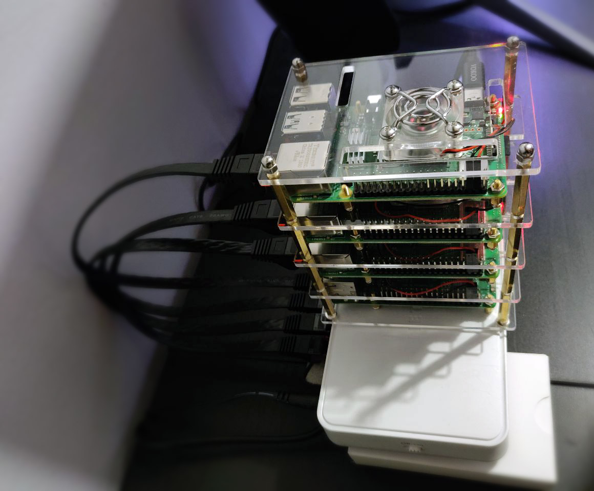
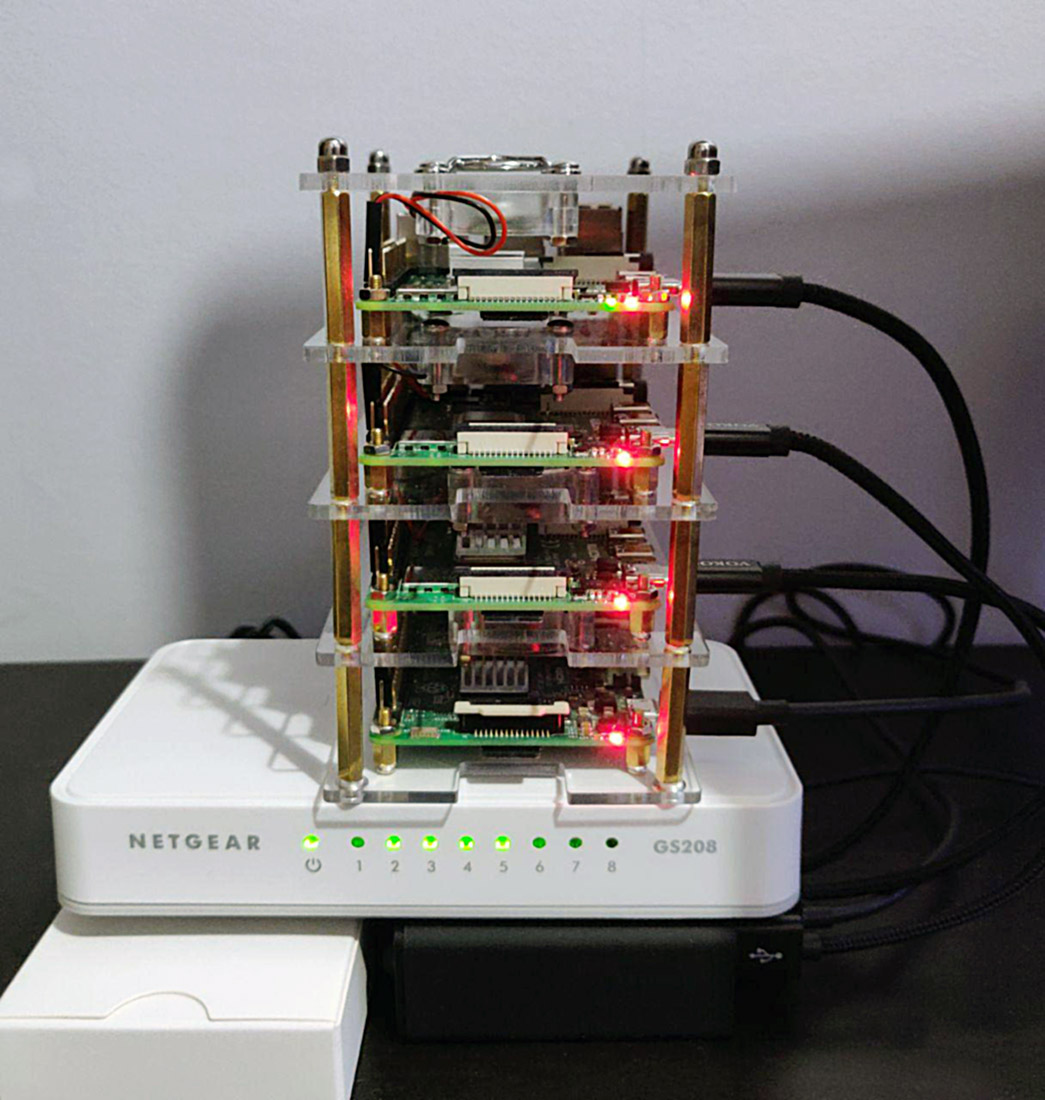
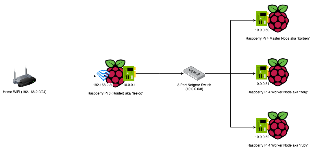
By now you should have 1 x Pi running as the dedicated Pi network router, DHCP, DNS and jumpbox, as well as 1 x Pi running as the cluster Master Node.

Of course it’s always best to have more than 1 x Master node, but as this is just an experimental/fun setup, one is just fine. The same applies to the Worker nodes, although in my case I added two workers with each Pi 4 having 4GB RAM.

Joining a Worker Node to the Cluster

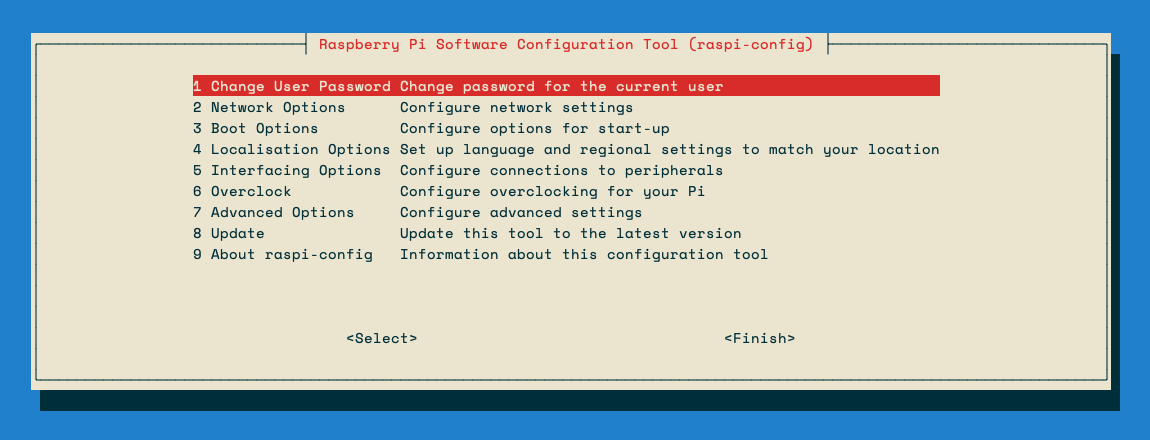
Start off by completing the setup steps as per the Common Setup section in Part 2 with your new Pi.

Once your new Worker Pi is ready and on the network with it’s own static DHCP lease, join it to the cluster (currently only the Master Node) by using the kubeadm join command you noted down when you first initialised your cluster in Part 2.

E.g.

sudo kubeadm join 10.0.0.50:6443 --token kjx8lp.wfr7n4ie33r7dqx2 \
     --discovery-token-ca-cert-hash sha256:25a997a1b37fb34ed70ff4889ced6b91aefbee6fb18e1a32f8b4c8240db01ec3

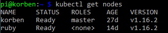
After a few moments, SSH back to your master node and run kubectl get nodes. You should see the new worker node added and after it pulls down and starts the weave net CNI image it’s status will change to Ready.

kubernetes worker node added to cluster

Setting up MetalLB

The problem with a ‘bare metal’ Kubernetes cluster (or any self-installed, manually configured k8s cluster for that matter) is that it doesn’t have any load-balancer implementation to handle LoadBalancer service types.

When you run Kubernetes on top of a cloud hosting platform like AWS or Azure, they are backed natively by load-balancer implementations that work seamlessly with those cloud platform’s load-balancer services. E.g. classic application or elastic load balancers with AWS.

However, with a Raspberry Pi cluster, you don’t have anything fancy like that to provide LoadBalancer services for your applications you run.

MetalLB provides a software based implementation that can work on a Pi cluster.

Install version 0.8.3 of MetalLB by applying the following manifest with kubectl:

kubectl apply -f https://gist.githubusercontent.com/Shogan/d418190a950a1d6788f9b168216f6fe1/raw/ca4418c7167a64c77511ba44b2c7736b56bdad48/metallb.yaml

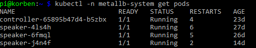
Make sure the MetalLB pods are now up and running in the metallb-system namespace that was created.

metallb pods running

Now you will create a ConfigMap that will contain the settings your MetalLB setup will use for the cluster load-balancer services.

Create a file called metallb-config.yaml with the following content:

apiVersion: v1
kind: ConfigMap
metadata:
  namespace: metallb-system
  name: config
data:
  config: |
    address-pools:
    - name: default
      protocol: layer2
      addresses:
      - 10.23.220.88-10.23.220.98

Update the addresses section to use whichever range of IP addresses you would like to assign for use with MetalLB. Note, I only used 10 addresses as below for mine.

Apply the configuration:

kubectl apply -f ./metallb-config.yaml

Setup Helm in the Pi Cluster

First of all you’ll need an ARM compatible version of Helm. Download it and move it to a directory that is in your system PATH. I’m using my Kubernetes master node as a convenient location to use kubectl and helm commands from, so I did this on my master node.

Install Helm Client

export HELM_VERSION=v2.9.1
wget https://kubernetes-helm.storage.googleapis.com/helm-$HELM_VERSION-linux-arm.tar.gz
tar xvzf helm-$HELM_VERSION-linux-arm.tar.gz
sudo mv linux-arm/helm /usr/bin/helm

Install Helm Tiller in the Cluster

Use the following command to initialise the tiller component in your Pi cluster.

helm init --tiller-image=jessestuart/tiller --service-account tiller --override spec.selector.matchLabels.'name'='tiller',spec.selector.matchLabels.'app'='helm' --output yaml | sed 's@apiVersion: extensions/v1beta1@apiVersion: apps/v1@' | kubectl apply -f -

Note: it uses a custom image from jessestuart/tiller (as this is ARM compatible). The command also replaces the older api spec for the deployment with the apps/v1 version, as the older beta one is no longer applicable with Kubernetes 1.16.

Deploy an Ingress Controller with Helm

Now that you have something to fulfill LoadBalancer service types (MetalLB), and you have Helm configured, you can deploy an NGINX Ingress Controller with a LoadBalancer service type for your Pi cluster.

helm install --name nginx-ingress stable/nginx-ingress --set rbac.create=true --set controller.service.type=LoadBalancer

If you list out your new ingress controller pods though you might find a problem with them running. They’ll likely be trying to use x86 architecture images instead of ARM. I manually patched my NGINX Ingress Controller deployment to point it at an ARM compatible docker image.

kubectl set image deployment/nginx-ingress-controller     nginx-ingress-controller=quay.io/kubernetes-ingress-controller/nginx-ingress-controller-arm:0.26.1

After a few moments the new pods should now show as running:

new nginx ingress pods running with ARM image

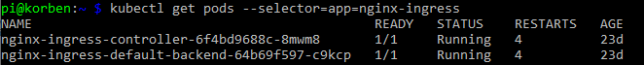
Now to test everything, you can grab the external IP that should have been assigned to your NGINX ingress controller LoadBalancer service and test the default NGINX backend HTTP endpoint that returns a simple 404 message.

List the service and get the EXTERNAL-IP (this should sit in the range you configured MetalLB with):

kubectl get service --selector=app=nginx-ingress

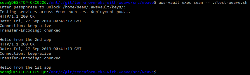
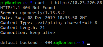
Curl the NGINX Ingress Controller LoadBalancer service endpoint with a simple GET request:

curl -i http://10.23.220.88

You’ll see the default 404 not found response which indicates that the controller did indeed receive your request from the LoadBalancer service and directed it appropriately down to the default backend pod.

the nginx default backend 404 response

Concluding

At this point you’ve configured:

  • A Raspberry Pi Kubernetes network Router / DHCP / DNS server / jumpbox
  • Kubernetes master node running the master components for the cluster
  • Kubernetes worker nodes
  • MetalLB load-balancer implementation for your cluster
  • Helm client and Tiller agent for ARM in your cluster
  • NGINX ingress controller

In part 1, recall you setup some iptables rules on the Router Pi as an optional step?

These PREROUTING AND POSTROUTING rules were to forward packets destined for the Router Pi’s external IP address to be forwarded to a specific IP address in the Kubernetes network. In actual fact, the example I provided was what I used to forward traffic from the Pi router all the way to my NGINX Ingress Controller load balancer service.

Revisit this section if you’d like to achieve something similar (access services inside your cluster from outside the network), and replace the 10.23.220.88 IP address in the example I provided with the IP address of your own ingress controller service backed by MetalLB in your cluster.

Also remember that at this point you can add as many worker nodes to the cluster as you like using the kubeadm join command used earlier.

Building a Raspberry Pi Kubernetes Cluster – Part 2 – Master Node

Building a Raspberry Pi Kubernetes Cluster - part 2 - master node title featured image

The Kubernetes Master node is one that runs what are known as the master processes: The kube-apiserver, kube-controller-manager and kube-scheduler.

In this post we’ll go through some common setup that all nodes (masters and workers) in your cluster should get, and then on top of that, the specific setup that will finally configure a single node in the cluster to be the master.

If you would like to jump to the other partes in this series, here are the links:

By now you should have some sort of stack or collection of Raspberry Pis going. As mentioned in the previous post, I used a Raspberry Pi 3 for my router/dhcp server for the Kubernetes Pi Cluster network, and Raspberry Pi 4’s with 4GB RAM each for the master and worker nodes. Here is how my stack looks now:

picture of raspberry pi devices in stack, forming the kubernetes cluster
The stack of Rasperry Pi’s in my cluster. Router Pi at the bottom, master and future worker nodes above. They’re sitting on top of the USB power hub and 8 port gigabit network switch

Common Setup

This setup will be used for both masters and workers in the cluster.

Start by writing the official Raspbian Buster Lite image to your microSD card. (I used the 26th September 2019 version), though as you’ll see next I also updated the Pi’s firmware and OS using the rpi-update command.

After attaching your Pi (master) to the network switch, it should pick up an IP address from the DHCP server you setup in part 1.

SSH into the Pi and complete the basic setup such as setting a hostname and ensuring it gets a static IP address lease from DHCP by editing your dnsmasq configuration (as per part 1).

Note: As the new Pi is running on a different network behind your Pi Router, you can either SSH into your Pi Router (like a bastion host or jump box) and then SSH into the new Master Pi node from there.

Now update it:

sudo rpi-update

After the update completes, reboot the Pi.

sudo reboot now

SSH back into the Pi, then download and install Docker. I used version 19.03 here, though at the moment it is not ‘officially’ supported.

export VERSION=19.03
curl -sSL get.docker.com | sh && sudo usermod pi -aG docker && newgrp docker

Kubernetes nodes should have swap disabled, so do that next. Additionally, you’ll enable control groups (cgroups) for resource isolation.

sudo dphys-swapfile swapoff
sudo dphys-swapfile uninstall
sudo update-rc.d dphys-swapfile remove
sudo systemctl disable dphys-swapfile.service

sudo sed -i -e 's/$/ cgroup_enable=cpuset cgroup_memory=1 cgroup_enable=memory/' /boot/cmdline.txt

Installing kubeadm and other Kubernetes components

Next you’ll install the kubeadm tool (helps us create our cluster quickly), as well as a bunch of other components required, such as the kubelet (the main node agent that registers nodes with the API server among other things), kubectl and the kubernetes cni (to provision container networking).

Next up, install the legacy iptables package and setup networking so that it traverses future iptables rules.

Note: when I built my cluster initially I discovered problems with iptables later on, where the kube-proxy and kubelet services had trouble populating all their required iptables rules using the pre-installed version of iptables. Switching to legacy iptables fixed this.

The error I ran into (hopefully those searching it will come across this post too) was:

proxier.go:1423] Failed to execute iptables-restore: exit status 2 (iptables-restore v1.6.0: Couldn't load target `KUBE-MARK-DROP':No such file or directory

Setup iptables and change it to the legacy version:

sudo sysctl net.bridge.bridge-nf-call-iptables=1
sudo update-alternatives --set iptables /usr/sbin/iptables-legacy

Lastly to finish off the common (master or worker) node setup, reboot.

sudo reboot now

Master Node Setup

Now you can configure this Pi as a master Kubernetes node. SSH back in after the reboot and pull down the various node component docker images, then initialise it.

Important: Make sure you change the 10.0.0.50 IP address in the below code snippet to match whatever IP address you reserved for this master node in your dnsmasq leases configuration. This is the IP address that the master API server will advertise out with.

Note: In my setup I am using 192.168.0.0./16 as the pod CIDR (overlay network). This is specifically to keep it separate from my internal Pi network of 10.0.0.0/8.

sudo kubeadm config images pull -v3
sudo kubeadm init --token-ttl=0 --apiserver-advertise-address=10.0.0.50 --pod-network-cidr=192.168.0.0/16

# capture text and run as normal user. e.g.:
# mkdir -p $HOME/.kube
# sudo cp -i /etc/kubernetes/admin.conf $HOME/.kube/config
# sudo chown $(id -u):$(id -g) $HOME/.kube/config

Once the kubeadm commands complete, the init command will output a bunch of commands to run. Copy and enter them afterwards to setup the kubectl configuration under $HOME/.kube/config.

You’ll also see a kubeadm join command/token. Take note of that and keep it safe. You’ll use this to join other workers to the cluster later on.

kubeadm join 10.0.0.50:6443 --token yi4hzn.glushkg39orzx0fk \
    --discovery-token-ca-cert-hash sha256:xyz0721e03e1585f86e46e477de0bdf32f59e0a6083f0e16871ababc123

Installing the CNI (Weave)

You’ll setup Weave Net next. At a high level, Weave Net creates a virtual container network that connects your containers that are scheduled across (potentially) many different hosts and enables their automatic discovery across these hosts too.

Kubernetes has a pluggable architecture for container networking, and Weave Net is one implementation of this.

Note: the command below assumes you’re using an overlay/container network of 192.168.0.0/16. Change this if you’re not using this range.

On your Pi master node:

curl --location -o ./weave-cni.yaml "https://cloud.weave.works/k8s/net?k8s-version=$(kubectl version | base64 | tr -d '\n')&env.IPALLOC_RANGE=192.168.0.0/16"
kubectl apply -f ./weave-cni.yaml

After a few moments waiting for your node to pull down the weave net container images, check that the weave container(s) are running and that the master node is showing as ready. Here is how that should look…

kubectl -n kube-system get pods
kubectl get nodes
pi@korben:~ $ kubectl -n kube-system get pods | grep weave
weave-net-cfxhr                  2/2     Running   20         10d
weave-net-chlgh                  2/2     Running   17         23d
weave-net-rxlg8                  2/2     Running   13         23d

pi@korben:~ $ kubectl get nodes
NAME     STATUS   ROLES    AGE   VERSION
korben   Ready    master   23d   v1.16.2

That is pretty much it for the master node setup. You now have a single master node running the Kubernetes master components / API server, and have even used to successfully provision and configure container networking.

As a result of deploying Weave Net, you now have a DaemonSet that will ensure that any new node that joins the cluster will automatically get the Weave Net CNI. All other nodes in the cluster will automatically update to ‘know’ about the new node and subsequently containers in the cluster will be able to talk to each other over the overlay network.

Building a Raspberry Pi Kubernetes Cluster – Part 1 – Routing

Building a Raspberry Pi Kubernetes Cluster - part 1 - routing - title featured image

I’ve recently built myself a Kubernetes (1.16.2) cluster running on a combination of Raspberry Pi 4 and 3 devices.

Raspberry Pi Cluster Stack

I’ll be running through the steps I took to build it out in this series, with part 1 focusing on the router and internal node network side of things.

If you want to jump to the other parts in this series:

First off, here is a list of parts I used to set everything up:

To make the setup as portable as possible, and also slightly seggregated from my home network, I used the 1 x Raspberry Pi 3 device I had as a router between my home network and my Kubernetes Layer 2 Network (effectively the devices on the 8 port Netgear Switch).

Here is a network diagram that shows the setup.

Raspberry Pi Kubernetes Network Diagram

Building the Raspberry Pi Cluster Router

Of course you’ll need an OS on the microSD card for each Raspberry Pi you’re going to be using. I used the latest Raspbian Buster Lite image from the official Raspbian Downloads page (September 26).

This is a minimal image and is exactly what we need. You’ll need to write it to your microSD card. There are plenty tutorials out there on doing this, so I won’t cover it here.

One piece of advice though, would be to create a file called “ssh” on the imaged card filesystem after writing the image. This enables you to SSH on directly without the need to connect up a screen and setup the SSH daemon yourself. Basically just login to your home network DHCP server and look for the device once it boots then SSH to it’s automatically assigned IP address.

Also, it would be wise to reserve an IP address on your home network’s DHCP service for your Pi Router. Grab the MAC address of your Pi and add it to your home network DHCP service’s reserved IP addresses. I set mine to 192.168.2.30 on my WiFi network.

List the wlan interface’s MAC address with:

ifconfig wlan0

Setting Hostname and Changing the Default Password

On the Router Raspberry Pi, run the following command to change the hostname to something other than “raspberry” and change the default password too:

sudo raspi-config
Change the default password and hostname of the Raspberry Pi

Setting up the Pi Router

Now the rest of the guide deserves much credit to this blog post, however, I did change a few things on my setup, as the routing was not configured 100% correctly to allow external access to services on the internal Kubernetes network.

I needed to add a couple of iptables rules in order to be able to access my Ingress Controller from my home network. More on that later though.

Interface Setup

You need to configure the WiFi interface (wlan0) and the Ethernet Interface (eth0) for each “side” of the network.

Edit the dhcpd.conf file and add an eth0 configuration right at the bottom, then save.

sudo nano /etc/dhcpcd.conf
interface eth0
static ip_address=10.0.0.1/8
static domain_name_servers=1.1.1.1,208.67.222.222
nolink

Of course replace the above DNS servers with whichever you prefer to use. I’ve used Cloudflare and OpenDNS ones here.

Next, setup your WiFi interface to connect to your home WiFi. WiFi connection details get saved to /etc/wpa_supplicant/wpa_supplicant.conf but it is best to use the built-in configuration tool (raspi-config) to do the WiFi setup.

sudo raspi-config

Go to Network Options and enter your WiFi details. Save/Finish afterwards.

Install and Configure dnsmasq

sudo apt update
sudo apt install dnsmasq
sudo mv /etc/dnsmasq.conf /etc/dnsmasq.conf.backup

Create a new /etc/dnsmasq.conf file with the below command:

The script is the main dnsmasq configuration that sets DHCP up over the eth0 interface (for the 10.0.0.0/8 network side) and configures some nameservers for DNS as well as a few other bits.

Edit the service file for dnsmasq (/etc/init.d/dnsmasq) to prevent issues with start-up order of dnsmasq and dhcpcd:

sudo nano /etc/init.d/dnsmasq

Change the top of the file to look like this:

#!/bin/sh

# Hack to wait until dhcpcd is ready
sleep 10

### BEGIN INIT INFO
# Provides:       dnsmasq
# Required-Start: $network $remote_fs $syslog $dhcpcd
# Required-Stop:  $network $remote_fs $syslog
# Default-Start:  2 3 4 5
# Default-Stop:   0 1 6
# Description:    DHCP and DNS server
### END INIT INFO

The lines changed above are the sleep 10 command and the Required-Start addition of $dhcpcd.

At this point its a good idea to reboot.

sudo reboot now

After the reboot, check that dnsmasq is running.

sudo systemctl status dnsmasq

Setup iptables

First of all, enable IP forwarding. Edit the /etc/sysctl.conf file and uncomment this line:

net.ipv4.ip_forward=1

This enables us to use NAT rules with iptables.

Now you’ll configuring some POSTROUTING and FORWARD rules in iptables to allow your Raspberry Pi devices on the 10.0.0.0/8 network to access the internet via your Pi Router’s wlan0 interface.

sudo iptables -t nat -A POSTROUTING -o wlan0 -j MASQUERADE
sudo iptables -A FORWARD -i wlan0 -o eth0 -m state --state RELATED,ESTABLISHED -j ACCEPT
sudo iptables -A FORWARD -i eth0 -o wlan0 -j ACCEPT

Optional Step

This is optional, and you might only need to do this later on once you start running services in your Kubernetes Pi Cluster.

Forward Traffic from your home network to a Service or Node IP in your Cluster Network:

sudo iptables -t nat -A PREROUTING -i wlan0 -p tcp --dport 80 -j DNAT --to-destination 10.23.220.88:80
sudo iptables -t nat -A POSTROUTING -p tcp -d 10.23.220.88 --dport 80 -j SNAT --to-source 10.0.0.1

The above assumes a couple of things that you should change accordingly (if you use this optional step):

  • You have a Service running in the Kubnernetes network, listening on port 80 (http) on IP 10.23.220.88
  • You setup your Pi Router to use 10.0.0.1 as the eth0 device IP (as per above in this post), and your wlan0 interface is the connection that your Pi router is using to connect to your home network (WiFi).
  • You actually want to forward traffic hitting your Pi Router (from the WiFi wlan0 interface) through the 10.0.0.1 eth0 interface and into a service IP on the 10.0.0.0/8 network. (In my example above I have an nginx Ingress Controller running on 10.23.220.88).

Persisting your iptables rules across reboots

Persist all of your iptables rules by installing iptables-persistent:

sudo apt install iptables-persistent

The above will run a wizard after installation and you’ll get the option to save your IPv4 rules. Choose Yes, then reboot afterwards.

After reboot, run sudo iptables -L -n -v to check that the rules persisted after reboot.

Note: if you ever update your Pi Router’s iptables rules and want to re-save the new set of rules to persist across reboots, you’ll need to re-save them using the iptables-persistent package.

sudo dpkg-reconfigure iptables-persistent

Adding new Pi devices to your network in future

Whenever you add an additional Raspberry Pi device to the 8 port switch / Kubernetes network in the future, make sure you edit /etc/dnsmasq.conf to update the list of MAC addresses assigned to 10.0.0.x IP addresses.

You’ll want to set the new Pi’s eth0 MAC address up in the list of pre-defined DHCP leases.

You can also view the /var/lib/misc/dnsmasq.leases file to see the current dnsmasq DHCP leases.

This is handy when adding a new, un-configured Pi to the network – you can pick up the auto-assigned IP address here, and then SSH to that for initial configuration.

Concluding

That is pretty much the setup and configuration for the Pi Router complete. As mentioned above, much credit for this configuration goes to this guide on downey.io.

I ended up modifying the iptables rules for service traffic forwarding from my home network side into some Kubernetes LoadBalancer services I ended up running later on which I covered above in the Optional Steps section.

At this point you should have your Pi Router connected to your home network via WiFi, and have the Ethernet port plugged into your network switch. Make sure the switch is not connected back to your home network via an Ethernet cable or you’ll run into some strange network loop issues.

You should now be able to plug in new Pi’s to the network switch, and they should get automatically assigned DHCP addresses on the 10.0.0.0/8 network.

Updating your dnsmasq.conf file with the new Pi’s ethernet MAC addresses means that they can get statically leases IP addresses too, which you’ll need for your Kubernetes nodes once you start adding them (see Part 2 coming next).

Enabling and Using Ephemeral Containers on Kubernetes 1.16

Ephemeral Containers on Kubernetes 1.16

Ephemeral Containers are an early-state alpha feature in Kubernetes 1.16 and offer some interesting new dynamics when it comes to tooling that we can use in day-to-day Kubernetes operations.

To see this feature live, in action, check out the demo shell session below:

Before we look at Ephemeral Containers, let’s go over what a Pod is in the Kubernetes world.

Remember that a Pod in Kubernetes is a group of one or more containers (e.g. Docker containers).

With that basic tidbit of information out of the way, we’ll look at some characteristics that Pods and their containers have always had in the past:

  • They’re meant to be disposable and easily replaced in a controlled manner with Deployments.
  • You could not add containers to pods at runtime.
  • Containers in pods can have ports assigned for network access and use things like liveness probes.
  • Troubleshooting containers in pods usually meant looking at logs or using kubectl exec to get into the running container and poke around. The latter of course being useless if your container had already crashed.

So here is where I see one of the best use cases for the new Ephemeral Containers feature – troubleshooting.

Ephemeral Containers can be inserted into a live, running pod at runtime.

This means they are great for live troubleshooting of your applications. How many times have you wished your base docker image you’ve built your application image on top of has curl, dig, or even ping in some cases…

If we’ve been following best practices, we’ve kept our docker images as slim as possible, and removed as much attack surface area as possible. This usually means all the useful diagnostic tools are missing.

Ephemeral Containers are great. We can now keep a diagnostic Docker image handy with all the tools we need and live insert a diagnostic container into a running pod to troubleshoot when the time arises.

When an Ephemeral Container runs, it executes within the namespace of the target pod. So you’ll be able to access, for example, the filesystems and other resources that containers in the the pods have.

Demonstration

In order to follow along with this demo, you’ll need Kubernetes 1.16 or higher, and you’ll need to use two pod related features:

  • EphemeralContainers (of course) – disabled by default in 1.16 as it’s alpha.
  • PodShareProcessNamespace – for sharing the process namespace in a pod (enabled by default in 1.16 as it’s a beta feature).

To enable the Ephemeral Containers feature, edit the following configuration files on your Kubernetes master nodes and restart each master:

Enable the EphemeralContainers alpha feature gate in the following places

  • /etc/kubernetes/manifests/kube-apiserver.yaml
  • /etc/kubernetes/manifests/kube-scheduler.yaml

by adding the following line inside the command section:

--feature-gates=EphemeralContainers=true

Create a new pod (the one I’m using is Rabbit MQ and specific to ARM architecture as I’m using a Raspberry Pi cluster here), but replace this image with anything you like as its just for testing:

Save this as pod.yaml

apiVersion: v1
kind: Pod
metadata:
  name: rabbit
  labels:
    role: myrole
spec:
  shareProcessNamespace: true
  containers:
    - name: rabbitmq
      image: arm32v7/rabbitmq
      ports:
        - name: rabbit
          containerPort: 5672
          protocol: TCP

Create it with kubectl apply -f ./pod.yaml

Next, create an EphemeralContainer resource saving it as ephemeral-diagnostic-container.json

(Note that I’m using a Docker image I created, shoganator/rpi-alpine-tools with a bunch of diagnostic tools added, and that this image is specific to ARM architecture only). Replace the image in this file with anything else you like, e.g. busybox.

{
    "apiVersion": "v1",
    "kind": "EphemeralContainers",
    "metadata": {
            "name": "rabbit"
    },
    "ephemeralContainers": [{
        "command": [
            "bash"
        ],
        "image": "shoganator/rpi-alpine-tools",
        "imagePullPolicy": "Always",
        "name": "diagtools",
        "stdin": true,
        "tty": true,
        "terminationMessagePolicy": "File"
    }]
}

Apply this to your existing pod:

kubectl -n default replace --raw /api/v1/namespaces/default/pods/rabbit/ephemeralcontainers -f ./ephemeral-diagnostic-container.json

Describe your rabbit pod with kubectl describe pod rabbit

Ephemeral Containers:
   diagtools:
     Container ID:  docker://eb55c71f102ce3d56221934f6ebcabfd2da76204df718bd8d2573da24aecc8e9
     Image:         shoganator/rpi-alpine-tools
     Image ID:      docker-pullable://shoganator/rpi-alpine-tools@sha256:bb00f943d511c29cc2367183630940e797f5e9552683b672613bf4cb602a1c4c
     Port:          
     Host Port:     
     Command:
       bash
     State:          Running
       Started:      Sat, 16 Nov 2019 14:49:58 +0000
     Ready:          False
     Restart Count:  0
     Environment:    
     Mounts:         
 Conditions:
   Type              Status
   Initialized       True
   Ready             True
   ContainersReady   True
   PodScheduled      True

You can see now that the Ephemeral Containers section is populated with the newly running Ephemeral Container that we added into the rabbit pod.

The next step is to actually use this container to do some diagnosis / probing inside the pod. Attach to the diagtools ephemeral container inside the pod:

kubectl attach -it rabbit -c diagtools

Now you can list processes, ping items in the network, or maybe test another web service in your cluster from the context of this pod. E.g.

ps auxww
ping 192.168.192.13
curl http://hello-node1:8081
htop

Remember that with Ephemeral Containers:

  • Cannot have ports, so fields such as ports, livenessProbe, readinessProbe are not able to be used.
  • Setting resources is disallowed as pod resources are immutable.
    They will disappear if a pod is deleted/re-scheduled.

Definitive guide to using Weave Net CNI on AWS EKS

Looking to install the Weave Net CNI on AWS EKS / Kubernetes and remove the AWS CNI? Look no further. This guide will detail and demonstrate the process.

What this guide will cover

  • Removing AWS CNI plugin
  • Installing the Weave Net CNI on AWS EKS
  • Making sure your EC2 instances will work with Weave
  • Customising Weave Net CNI including custom pod overlay network ranges
  • Removing max-pods limit on your EKS worker nodes
  • Reconfiguring pods that don’t work after switching to Weave. (E.g. those that need to talk back to the EKS master nodes that do not get the Weave overlay network)

Want the Terraform source and test scripts to jump right in?

GitHub Terraform and test environment source

Otherwise, read on for step-by-step and more information…

There are a few guides floating around that detail how to install the Weave Net CNI plugin for Amazon Kubernetes clusters (EKS), however I’ve not seen them go into much detail.

Most tend to skip over some important steps and details when it comes to configuring weave and getting the pod networking functioning correctly.

There are also some important caveats that you should be aware of when replacing the AWS CNI Plugin with a different CNI, whether it be Weave, Calico, or any other.

Replacing CNI functionality

You should be 100% happy with what you’ll lose if completely replace the AWS CNI with another CNI. The AWS CNI has some very useful functionality such as:

  • Assigning IP addresses (via ENIs) to place pods directly into your VPC network
  • VPC flow logs that make sense

However, depending on your architecture and design decisions, as well as potential VPC network limitations, you may wish to opt out of the CNI that Amazon provides and instead use a different CNI that provides an overlay network with other functionality.

AWS CNI Limitations

One of the problems I have seen in VPCs is limited CIDR ranges, and therefore subnets that are carved up into smaller numbers of IP addresses.

The Amazon AWS CNI plugin is very IP address hungry and attaches multiple Secondary Private IP addresses to EKS worker nodes (EC2 instances) to provide pods in your cluster with directly assigned IPs.

This means that you can easily exhaust subnet IP addresses with just a few EKS worker nodes running.

This limitation also means that those who want high densities of pods running on worker nodes are in for a surprise. The IP address limit becomes an issue for maximum number of pods in these scenarios way before compute capacity becomes a problem.

This page shows the maximum number of ENI’s and Secondary IP addresses that can be used per EC2 instance: https://github.com/awslabs/amazon-eks-ami/blob/master/files/eni-max-pods.txt

Removing the AWS CNI plugin

Note: This process will involve you needing to replace your existing EKS worker nodes (if any) in the cluster after installing the Weave Net CNI.

Assuming you have a connection to your cluster already, the first thing to do is to remove the AWS CNI.

kubectl -n=kube-system delete daemonset aws-node

With that gone, your future EKS workers will no longer assign multiple Secondary IP addresses from your VPC subnets.

Installing CNI Genie

With the AWS CNI plugin removed, your pods won’t be able to get a network connection when starting up from this point onward.

Installing a basic deployment of CNI Genie is a quick way to get automatic CNI selection working for containers that start from this point on.

CNI genie has tons of other great features like allowing you to customise which CNI containers use when starting up and more.

For now, you’re just using it to allow containers to start-up and use the Weave Net overlay network by default.

Install CNI Genie. This manifest works with Kubernetes 1.12, 1.13, and 1.14 on EKS.

kubectl apply -f https://raw.githubusercontent.com/Shogan/terraform-eks-with-weave/master/src/weave/genie-plugin.yaml

Installing Weave

Before continuing, you should ensure your EC2 machines disable source/destination network checking.

Make this change in the userdata script that your instances run when starting from their autoscale groups.

REGION_ID=$(curl -s http://169.254.169.254/latest/meta-data/placement/availability-zone | grep -Po "(us|ca|ap|eu|sa)-(north|south)?(east|west|central)-[0-9]+")
aws ec2 modify-instance-attribute --instance-id $INSTANCE_ID --no-source-dest-check --region $REGION_ID

On to installing Weave Net CNI on AWS EKS…

Next, get a Weave Net CNI yaml manifest file. Decide what overlay network IP Range you are going to be using and fill it in for the env.IPALLOC_RANGE query string parameter value in the code block below before making the curl request.

curl --location -o ./weave-cni.yaml "https://cloud.weave.works/k8s/net?k8s-version=$(kubectl version | base64 | tr -d '\n')&env.IPALLOC_RANGE=192.168.0.0/16"

Note: the env.IPALLOC_RANGE query string param added is to specify you want a config with a custom CIDR range. This should be chosen specifically not to overlap with any network ranges shared with the VPC you’ll be deploying into.

In the example above I had a VPC and VPC peers that shared the CIDR block 10.0.0.0/8). Therefore I chose to use 192.168.0.0/16 for the Weave overlay network.

You should be aware of the network ranges you’re using and plan this out appropriately.

The config you now have as weave-cni.yaml will contain the environment variable IPALLOC_RANGE with the correct value that the weave pods will use to setup networking on the EKS Worker nodes.

Apply the weave Net CNI resources:

Note: This manifest is pre-created to use an overlay network range of 192.168.0.0/16

kubectl apply -f https://raw.githubusercontent.com/Shogan/terraform-eks-with-weave/master/src/weave/weave-cni.yaml

Note: Don’t expect things to change suddenly. The current EKS worker nodes will need to be rotated out (e.g. drain, terminate, wait for new to appear) in order for the IP addresses that the AWS CNI has kept warm/allocated to be released.

If you have any existing EKS workers running, drain them now and terminate/replace them with new workers. This includes the source/destination check change made previously.

kubectl get nodes
kubectl drain nodename --ignore-daemonsets

Remove max pod limits on nodes:

Your worker nodes by default have a limit set on how many pods they can schedule. The EKS AMI sets this based on EC2 type (and the max pods due to the usual ENI limitations / IP address limitations with the AWS CNI).

Check your max pod limits with:

kubectl get nodes -o yaml | grep pods

If you’re using the standard EKS optimized AMI (or a derivative of it) then you can simply pass an option to the bootstrap.sh script located in the image that setup the kubelet and joins the cluster. Set –use-max-pods false as an argument to the script.

For example, your autoscale group launch configuration might get the EC2 worker nodes to join the cluster using the bootstrap.sh script. You can update it like so:

/etc/eks/bootstrap.sh --b64-cluster-ca 'YOUR_BASE64_CLUSTER_CA_DATA_HERE' --apiserver-endpoint 'https://YOUR_EKS_CLUSTER_ENDPOINT_HERE' --use-max-pods false --kubelet-extra-args '' 'YOUR_CLUSTER_NAME_HERE'

If you’re using the EKS Terraform module you can simply pass in bootstrap-extra-args – this will automatically setup your worker node userdata templates with extra bootstrap arguments for the kubelet. See example here

Checking max-pods limit again after applying this change, you should see the previous pod limit (based on prior AWS CNI max pods for your instance type) removed now.

You’re almost running Weave Net CNI on AWS EKS, but first you need to roll out new worker nodes.

With the Weave Net CNI installed, the kubelet service updated and your EC2 source/destination checks disabled, you can rotate out your old EKS worker nodes, replacing them with the new nodes.

kubectl drain node --ignore-daemonsets

Once the new nodes come up and start scheduling pods, if everything went to plan you should see that new pods are using the Weave overlay network. E.g. 192.168.0.0/16.

A quick run-down on weave IP addresses and routes

If you get a shell to a worker node running the weave overlay network and do a listing of routes, you might see something like the following:

# ip route show
default via 10.254.109.129 dev eth0
10.254.109.128/26 dev eth0 proto kernel scope link src 10.254.109.133
169.254.169.254 dev eth0
192.168.0.0/16 dev weave proto kernel scope link src 192.168.192.0 

This routing table shows two main interfaces in use. One from the host (EC2) instance network interfaces itself, eth0, and one from weave called weave.

When network packets are destined for the 10.254.109.128/26 address space, then traffic is routed down eth0.

If traffic on the host is destined for any address on 192.168.0.0/16, it will instead route via the weave interface ‘weave’ and the weave system will handle routing that traffic appropriately.

Otherwise if the traffic is destined for some public IP address out on the wider internet, it’ll go down the default route which is down the interface, eth0. This is a default gateway in the VPC subnet in this case – 10.254.109.129.

Finally, metadata URL traffic for 169.254.169.254 goes down the main host eth0 interface of course.

Caveats

For the most part everything should work great. Weave will route traffic between it’s overlay network and your worker node’s host network just fine.

However, some of your custom workloads or kubernetes tools might not like being on the new overlay network. For example they might need to talk to other Kubernetes nodes that do not run weave net.

This is now where the limitation of using a managed Kubernetes offering like EKS becomes a bit of a problem.

You can’t run weave on the Kubernetes master / API servers that are effectively the ‘managed’ control plane that AWS EKS hosts for you.

This means that your weave overlay network does not span the Kubernetes master nodes where the Kubernetes API runs.

If you have an application or container in the weave overlay network and the Kubernetes master node / API needs to talk to it, this won’t work.

One potential solution though is to use hostNetwork: true in your pod specification. However you should of course be aware of how this would affect your application and application security.

In my case, I was running metrics-server and it stopped working after it started using Weave. I found out that the Kubernetes API needs to talk to the metrics-server service and of course this won’t work in the overlay network.

Example EKS with Weave Net CNI cluster

You can use the source code I’ve uploaded here.

There are five simple steps to deploy this example EKS cluster in your own account.

  • Modify the example.tfvars file to fit your own parameters.
  • terraform plan -var-file="example.tfvars" -out="example.tfplan"
  • terraform apply "example.tfplan"
  • ./setup-weave.sh
  • ./test-weave.sh

Warning: This will create a new VPC, subnets, NAT Gateway instance, Internet Gateway, EKS Cluster, and set of worker node autoscale groups. So be sure Terraform Destroy this if you’re just testing things out.

– Your wallet

After terraform creates all the resources, you can run the two included shell scripts. setup-weave.sh will remove the AWS CNI, install CNI genie, Weave, and deploy two simple example pods and services.

At this point you should terminate your existing worker nodes (that still use the AWS CNI) and wait for your new worker nodes to join the cluster.

test-weave.sh will wait for the hello-node test pods to become ready, and then execute a curl command inside one, talking to the other via the the service and vice versa. If successful, you’ll see a HTTP 200 OK response from each service.