Definitive guide to using Weave Net CNI on AWS EKS

Looking to install the Weave Net CNI on AWS EKS / Kubernetes and remove the AWS CNI? Look no further. This guide will detail and demonstrate the process.

What this guide will cover

  • Removing AWS CNI plugin
  • Installing the Weave Net CNI on AWS EKS
  • Making sure your EC2 instances will work with Weave
  • Customising Weave Net CNI including custom pod overlay network ranges
  • Removing max-pods limit on your EKS worker nodes
  • Reconfiguring pods that don’t work after switching to Weave. (E.g. those that need to talk back to the EKS master nodes that do not get the Weave overlay network)

Want the Terraform source and test scripts to jump right in?

GitHub Terraform and test environment source

Otherwise, read on for step-by-step and more information…

There are a few guides floating around that detail how to install the Weave Net CNI plugin for Amazon Kubernetes clusters (EKS), however I’ve not seen them go into much detail.

Most tend to skip over some important steps and details when it comes to configuring weave and getting the pod networking functioning correctly.

There are also some important caveats that you should be aware of when replacing the AWS CNI Plugin with a different CNI, whether it be Weave, Calico, or any other.

Replacing CNI functionality

You should be 100% happy with what you’ll lose if completely replace the AWS CNI with another CNI. The AWS CNI has some very useful functionality such as:

  • Assigning IP addresses (via ENIs) to place pods directly into your VPC network
  • VPC flow logs that make sense

However, depending on your architecture and design decisions, as well as potential VPC network limitations, you may wish to opt out of the CNI that Amazon provides and instead use a different CNI that provides an overlay network with other functionality.

AWS CNI Limitations

One of the problems I have seen in VPCs is limited CIDR ranges, and therefore subnets that are carved up into smaller numbers of IP addresses.

The Amazon AWS CNI plugin is very IP address hungry and attaches multiple Secondary Private IP addresses to EKS worker nodes (EC2 instances) to provide pods in your cluster with directly assigned IPs.

This means that you can easily exhaust subnet IP addresses with just a few EKS worker nodes running.

This limitation also means that those who want high densities of pods running on worker nodes are in for a surprise. The IP address limit becomes an issue for maximum number of pods in these scenarios way before compute capacity becomes a problem.

This page shows the maximum number of ENI’s and Secondary IP addresses that can be used per EC2 instance: https://github.com/awslabs/amazon-eks-ami/blob/master/files/eni-max-pods.txt

Removing the AWS CNI plugin

Note: This process will involve you needing to replace your existing EKS worker nodes (if any) in the cluster after installing the Weave Net CNI.

Assuming you have a connection to your cluster already, the first thing to do is to remove the AWS CNI.

kubectl -n=kube-system delete daemonset aws-node

With that gone, your future EKS workers will no longer assign multiple Secondary IP addresses from your VPC subnets.

Installing CNI Genie

With the AWS CNI plugin removed, your pods won’t be able to get a network connection when starting up from this point onward.

Installing a basic deployment of CNI Genie is a quick way to get automatic CNI selection working for containers that start from this point on.

CNI genie has tons of other great features like allowing you to customise which CNI containers use when starting up and more.

For now, you’re just using it to allow containers to start-up and use the Weave Net overlay network by default.

Install CNI Genie. This manifest works with Kubernetes 1.12, 1.13, and 1.14 on EKS.

kubectl apply -f https://raw.githubusercontent.com/Shogan/terraform-eks-with-weave/master/src/weave/genie-plugin.yaml

Installing Weave

Before continuing, you should ensure your EC2 machines disable source/destination network checking.

Make this change in the userdata script that your instances run when starting from their autoscale groups.

REGION_ID=$(curl -s http://169.254.169.254/latest/meta-data/placement/availability-zone | grep -Po "(us|ca|ap|eu|sa)-(north|south)?(east|west|central)-[0-9]+")
aws ec2 modify-instance-attribute --instance-id $INSTANCE_ID --no-source-dest-check --region $REGION_ID

On to installing Weave Net CNI on AWS EKS…

Next, get a Weave Net CNI yaml manifest file. Decide what overlay network IP Range you are going to be using and fill it in for the env.IPALLOC_RANGE query string parameter value in the code block below before making the curl request.

curl --location -o ./weave-cni.yaml "https://cloud.weave.works/k8s/net?k8s-version=$(kubectl version | base64 | tr -d '\n')&env.IPALLOC_RANGE=192.168.0.0/16"

Note: the env.IPALLOC_RANGE query string param added is to specify you want a config with a custom CIDR range. This should be chosen specifically not to overlap with any network ranges shared with the VPC you’ll be deploying into.

In the example above I had a VPC and VPC peers that shared the CIDR block 10.0.0.0/8). Therefore I chose to use 192.168.0.0/16 for the Weave overlay network.

You should be aware of the network ranges you’re using and plan this out appropriately.

The config you now have as weave-cni.yaml will contain the environment variable IPALLOC_RANGE with the correct value that the weave pods will use to setup networking on the EKS Worker nodes.

Apply the weave Net CNI resources:

Note: This manifest is pre-created to use an overlay network range of 192.168.0.0/16

kubectl apply -f https://raw.githubusercontent.com/Shogan/terraform-eks-with-weave/master/src/weave/weave-cni.yaml

Note: Don’t expect things to change suddenly. The current EKS worker nodes will need to be rotated out (e.g. drain, terminate, wait for new to appear) in order for the IP addresses that the AWS CNI has kept warm/allocated to be released.

If you have any existing EKS workers running, drain them now and terminate/replace them with new workers. This includes the source/destination check change made previously.

kubectl get nodes
kubectl drain nodename --ignore-daemonsets

Remove max pod limits on nodes:

Your worker nodes by default have a limit set on how many pods they can schedule. The EKS AMI sets this based on EC2 type (and the max pods due to the usual ENI limitations / IP address limitations with the AWS CNI).

Check your max pod limits with:

kubectl get nodes -o yaml | grep pods

If you’re using the standard EKS optimized AMI (or a derivative of it) then you can simply pass an option to the bootstrap.sh script located in the image that setup the kubelet and joins the cluster. Set –use-max-pods false as an argument to the script.

For example, your autoscale group launch configuration might get the EC2 worker nodes to join the cluster using the bootstrap.sh script. You can update it like so:

/etc/eks/bootstrap.sh --b64-cluster-ca 'YOUR_BASE64_CLUSTER_CA_DATA_HERE' --apiserver-endpoint 'https://YOUR_EKS_CLUSTER_ENDPOINT_HERE' --use-max-pods false --kubelet-extra-args '' 'YOUR_CLUSTER_NAME_HERE'

If you’re using the EKS Terraform module you can simply pass in bootstrap-extra-args – this will automatically setup your worker node userdata templates with extra bootstrap arguments for the kubelet. See example here

Checking max-pods limit again after applying this change, you should see the previous pod limit (based on prior AWS CNI max pods for your instance type) removed now.

You’re almost running Weave Net CNI on AWS EKS, but first you need to roll out new worker nodes.

With the Weave Net CNI installed, the kubelet service updated and your EC2 source/destination checks disabled, you can rotate out your old EKS worker nodes, replacing them with the new nodes.

kubectl drain node --ignore-daemonsets

Once the new nodes come up and start scheduling pods, if everything went to plan you should see that new pods are using the Weave overlay network. E.g. 192.168.0.0/16.

A quick run-down on weave IP addresses and routes

If you get a shell to a worker node running the weave overlay network and do a listing of routes, you might see something like the following:

# ip route show
default via 10.254.109.129 dev eth0
10.254.109.128/26 dev eth0 proto kernel scope link src 10.254.109.133
169.254.169.254 dev eth0
192.168.0.0/16 dev weave proto kernel scope link src 192.168.192.0 

This routing table shows two main interfaces in use. One from the host (EC2) instance network interfaces itself, eth0, and one from weave called weave.

When network packets are destined for the 10.254.109.128/26 address space, then traffic is routed down eth0.

If traffic on the host is destined for any address on 192.168.0.0/16, it will instead route via the weave interface ‘weave’ and the weave system will handle routing that traffic appropriately.

Otherwise if the traffic is destined for some public IP address out on the wider internet, it’ll go down the default route which is down the interface, eth0. This is a default gateway in the VPC subnet in this case – 10.254.109.129.

Finally, metadata URL traffic for 169.254.169.254 goes down the main host eth0 interface of course.

Caveats

For the most part everything should work great. Weave will route traffic between it’s overlay network and your worker node’s host network just fine.

However, some of your custom workloads or kubernetes tools might not like being on the new overlay network. For example they might need to talk to other Kubernetes nodes that do not run weave net.

This is now where the limitation of using a managed Kubernetes offering like EKS becomes a bit of a problem.

You can’t run weave on the Kubernetes master / API servers that are effectively the ‘managed’ control plane that AWS EKS hosts for you.

This means that your weave overlay network does not span the Kubernetes master nodes where the Kubernetes API runs.

If you have an application or container in the weave overlay network and the Kubernetes master node / API needs to talk to it, this won’t work.

One potential solution though is to use hostNetwork: true in your pod specification. However you should of course be aware of how this would affect your application and application security.

In my case, I was running metrics-server and it stopped working after it started using Weave. I found out that the Kubernetes API needs to talk to the metrics-server service and of course this won’t work in the overlay network.

Example EKS with Weave Net CNI cluster

You can use the source code I’ve uploaded here.

There are five simple steps to deploy this example EKS cluster in your own account.

  • Modify the example.tfvars file to fit your own parameters.
  • terraform plan -var-file="example.tfvars" -out="example.tfplan"
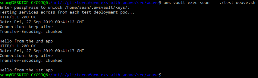
  • terraform apply "example.tfplan"
  • ./setup-weave.sh
  • ./test-weave.sh

Warning: This will create a new VPC, subnets, NAT Gateway instance, Internet Gateway, EKS Cluster, and set of worker node autoscale groups. So be sure Terraform Destroy this if you’re just testing things out.

– Your wallet

After terraform creates all the resources, you can run the two included shell scripts. setup-weave.sh will remove the AWS CNI, install CNI genie, Weave, and deploy two simple example pods and services.

At this point you should terminate your existing worker nodes (that still use the AWS CNI) and wait for your new worker nodes to join the cluster.

test-weave.sh will wait for the hello-node test pods to become ready, and then execute a curl command inside one, talking to the other via the the service and vice versa. If successful, you’ll see a HTTP 200 OK response from each service.

Kubernetes Ingress Controller with NGINX Reverse Proxy and Wildcard SSL from Let’s Encrypt

This is a pattern I’ve used with success for access to apps running in a number of Kubernetes clusters that were restricted to only having a single kubernetes ingress load balancer.

The Scenario

  • Kubernetes clusters (EKS) are on the internal network only (in this case private subnets in an AWS VPC).
  • IAM permissions are locked down to prevent creation of security groups (we can only use existing, pre-defined security groups) and so the LoadBalancer service type of Kubernetes is off-limits, as the k8s control plane needs to be able to create these automatically with security groups – this operation fails because of the restricted IAM permissions on the cluster. We have one Elastic Load Balancer created with the LoadBalancer service type when the cluster was initial bootstrapped with an nginx ingress controller + service type == LoadBalancer before the permissions were locked down again.
  • The Ingress Controller that is running is backed by an internal facing Elastic Load Balancer (ELB), created initially as described above.
  • Applications run across namespaces in each cluster, and the Ingress Controller must be able to provide dynamic access for users of these internal applications that sit on the network outside the k8s cluster.
  • DNS and ingress must be dynamic enough to allow the same apps to run in different namespaces, use the same URL path, but with differing hostnames. SSL must also be provided for all of these apps using a wildcard SSL certificate. E.g.
    • namespace1.cluster.foo.bar/app1
    • namespace2.cluster.foo.bar/app1
    • namespace3.cluster.foo.bar/app1
    • namespace1.cluster.foo.bar/app2
    • namespace2.cluster.foo.bar/app2
    • namespace3.cluster.foo.bar/app2
  • Once DNS wildcard CNAME record is created, it is difficult to change to point to a new location if needing changes (reliant on 3rd party to manage DNS).

A Solution with Reverse Proxying

There are of course a number of ways to approach this, like running under cert-manager inside the cluster with the letsencrypt issuer, or if you are running your own PKI with vault, the vault issuer.

cert-manager wouldn’t work well here as services are not publicly accessible for HTTP-01 certificate verification.

It could also be possible to terminate SSL at the ingress controller level in the cluster with the SSL certificate loaded there.

One additional requirement that I didn’t mention above though was that developers who are pushing their apps into the clusters need to be able to ‘dynamically’ configure their own personal ‘dev’ namespaces / ingress rules.

They configure their ingress easily enough with the Kubernetes Ingress resource when they deploy their apps (using Helm), however hostnames are not so easy for them to configure. Route53 is not in use here, and not allowed in this environment, and programmatic access to DNS is not possible.

A reverse proxy with NGINX

This layer exists more or less just to allow easy re-pointing of CNANE wildcard DNS entry to the Kubernetes cluster. As DNS is not easily configured (handled by another team/resource), we can simply leave it pointed to the NGINX elastic load balancer, and then just re-point requests using NGINX configuration if we need to.

It’s worth pointing out that this NGINX layer could be hosted on a multitude of places, including as a containerised solution, or it could even be replaced by a lambda function with API Gateway that could do the reverse proxying instead.

diagram showing flow of traffic from dns all the way through to pod via ingress controller.

Environments are designated by namespaces in each ‘class’ of cluster. For example a non-production EKS cluster will have namespaces for non-production environments.

Hostnames need to be used to help the ingress rules match correctly with designated paths.

I configured an internal load balancer and setup a fleet of NGINX instances behind it.

Here is a quick runbook of how to setup NGINX and certbot on a vanilla Amazon Linux 2 EC2 instance. Use whichever automation you prefer such as baking your own AMI with packer, using Terraform, or ansible, but the runbook of steps to install NGINX and certbot is effectively:

# nginx
sudo amazon-linux-extras install nginx1.12
sudo systemctl enable nginx
sudo systemctl start nginx

# certbot
sudo wget -r --no-parent -A 'epel-release-*.rpm' https://dl.fedoraproject.org/pub/epel/7/x86_64/Packages/e/
sudo rpm -Uvh dl.fedoraproject.org/pub/epel/7/x86_64/Packages/e/epel-release-*.rpm
sudo yum-config-manager --enable epel*
yum repolist all
yum install -y certbot

# request / generate letsencrypt wildcard cert using dns challenge interactively
certbot -d *.your.domain.here --manual --preferred-challenges dns certonly
# Interactive command above, choose to omit this in automation and do manually if you're using DNS-01 like I am here - certbot will give you a dynamically generated TXT record value for DNS-01 that you'll need to create.
systemctl restart nginx

Once NGINX is installed and your certs are generated, you’ll need to configure /etc/nginx/nginx.conf to point to the correct certificate files.
A wildcard CNAME record is created once-off that points anyhost.cluster.foo.bar to the internal ELB hostname for the reverse proxy NGINX instances (these sit outside of the cluster as standard EC2 hosts for now). For example:

[CNAME] *.cluster.foo.bar -> internal-nginx-reverse-proxy-fleet-xxxx-xxxx.us-east-2.elb.amazonaws.com

I used certbot (letsencrypt) to issue a wildcard SSL certificate for the NGINX fleet servers for *.cluster.foo.bar. DNS-01 challenge type was used, as everything here is in a private, internal network, not accessible by letsencrypt services.

A TXT record just needs to be created with your DNS to verify to letsencrypt that you own the domain in question.

In the NGINX configuration, the generated certificate is loaded up for port 443 and the following location rule is setup to proxy_pass the requests sent to the NGINX fleet back to the Kubernetes Ingress Controller ELB.

location / {
  proxy_set_header Host $host;
  proxy_pass http://internal-ingress-controller-xxxxx.us-east-2.elb.amazonaws.com;
}

The proxy_set_header directive is important, as it adds the host header that the NGINX fleet instance receives from the client, and sends it with the proxied request back to the Kubernetes ingress controller. The ingress rules need to match both hostname AND path in the requests to find the correct service inside the cluster/namespace.

SSL is now effectively terminated at the NGINX fleet layer with a wildcard SSL certificate and services inside the cluster don’t need to worry about configuring their own individual SSL certificates.

Ingress Rule Configuration

Now, developers can deploy their apps, and customise their ingress rules to use both hostname and path to setup access for their apps running in the cluster(s).

For example:

apiVersion: extensions/v1beta1
kind: Ingress
metadata:
  annotations:
    kubernetes.io/ingress.class: nginx
  labels:
    app: some-app
  name: some-app
  namespace: namespace1
spec:
  rules:
  - host: namespace1.cluster.foo.bar
    http:
      paths:
      - backend:
          serviceName: app1
          servicePort: 8083
        path: /app1
}

There are definitely other ways of doing this. Cleaner possibly, more automated in some ways, however with the constraints in play here (internal EKS, private only networks, no public internet access into the cluster), I think this is a good solution that makes life fairly pleasant for the developers that need to deploy their apps to these Kubernetes clusters.

Customising your EKS cluster DNS and the CoreDNS vs KubeDNS configuration differences

In the past I’ve used the excellent kops to build out Kubernetes clusters. The standard builds always made use of the kube-dns cluster addon. With EKS and CoreDNS things are a little different.

With kube-dns, I got used to using configMaps to customise DNS upstream servers and stub domains using the standard kube-dns configuration format which looks something like this:

apiVersion: v1
kind: ConfigMap
metadata:
  name: kube-dns
  namespace: kube-system
data:
  stubDomains: |
    {"ec2.internal": ["10.0.0.2"], "shogan.co.uk": ["10.20.0.200"]}
  upstreamNameservers: |
    ["8.8.8.8", "8.8.4.4"]

Amazon EKS and CoreDNS

However recently I’ve started doing a fair bit of Kubernetes cluster setups and configurations using Amazon EKS. I found that EKS and CoreDNS is now the standard and requires a different kind of configuration format which looks something like this:

apiVersion: v1
data:
  Corefile: |
    .:53 {
        errors
        health
        kubernetes cluster.local in-addr.arpa ip6.arpa {
          pods insecure
          upstream
          fallthrough in-addr.arpa ip6.arpa
        }
        prometheus :9153
        proxy . /etc/resolv.conf
        cache 30
        loop
        reload
        loadbalance
    }
    shogan.co.uk:53 {
        errors
        cache 30
        forward . 10.20.0.200
    }
    ec2.internal:53 {
        errors
        cache 30
        forward . 10.0.0.2
    }
kind: ConfigMap
metadata:
  labels:
    eks.amazonaws.com/component: coredns
    k8s-app: kube-dns
  name: coredns
  namespace: kube-system

To add your own custom stub domain nameservers with CoreDNS, the task becomes a case of editing the CoreDNS ConfigMap called coredns in the kube-system namespace.

Add your stub domain configuration blocks after the default .:53 section, with the forward property pointing to your custom DNS nameserver.

Once you’re done adding the new configuration, restart your CoreDNS containers. You can do this gracefully by executing the following in your CoreDNS containers:

kubectl exec -n kube-system coredns-pod-name-x -- kill -SIGUSR1 1

Alternatively, roll your CoreDNS pods one at a time.

Last of all, you’ll want to test the name resolution in a test container using a tool like dig. Your container /etc/resolv.conf files should usually be pointing at the IP address of your CoreDNS Cluster Service. So they’ll talk to the CoreDNS service for their usual look up queries, and CoreDNS should now be able to resolve your custom stub domain records but referring to your custom forwarded nameservers.

Apart from the different configuration format, there seem to be some fairly significant differences between CoreDNS and kube-dns. In my opinion, it would seem that overall CoreDNS is the better, more modern choice. Some of the benefits it enjoys over kube-dns are:

  • CoreDNS has multi-threaded design (leveraging Go)
  • CoreDNS uses negative caching whereas kube-dns does not (this means CoreDNS can cache failed DNS queries as well as successful ones, which overall should equal better speed in name resolution). It also helps with external lookups.
  • CoreDNS has a lower memory requirement, which is great for clusters with smaller worker nodes

Hopefully this helps when it comes to configuring EKS and CoreDNS. For more information, there is a great article that goes into the details of the differences of CoreDNS and kube-dns here.

Troubleshooting Amazon EKS Worker Nodes not joining the cluster

mechanic underneath car fixing things

I’ve recently been doing a fair bit of automation work on bringing up AWS managed Kubernetes clusters using Terraform (with Packer for building out the worker group nodes). Read on for some handy tips on troubleshooting EKS worker nodes.

Some of my colleagues have not worked with EKS (or Kubernetes) much before and so I’ve also been sharing knowledge and helping others get up to speed. A colleague was having trouble with their newly provisioned personal test EKS cluster found that the kube-system / control plane related pods were not starting.  I assisted with the troubleshooting process and found the following…

Upon diving into the logs of the kube-system related pods (dns, aws CNI, etc…) it was obvious that the pods were not being scheduled on the brand new cluster. The next obvious command to run was kubectl get nodes -o wide to take a look at the general state of the worker nodes.

Unsurprisingly there were no nodes in the cluster.

Troubleshooting worker nodes not joining the cluster

The first thing that comes to mind when you have worker nodes that are not joining the cluster on startup is to check the bootstrapping / startup scripts. In EKS’ case (and more specifically EC2) the worker nodes should be joining the cluster by running a couple of commands in the userdata script that the EC2 machines run on launch.

If you’re customising your worker nodes with your own custom AMI(s) then you’ll most likely be handling this userdata script logic yourself, and this is the first place to check.

The easiest way of checking userdata script failures on an EC2 instance is to simply get the cloud-init logs direct from the instance. Locate the EC2 machine in the console (or the instance-id inspect the logs for failures on the section that logs execution of your userdata script.

  • In the EC2 console: Right-click your EC2 instance -> Instance Settings -> Get System Log.
  • On the instance itself:
    • cat /var/log/cloud-init.log | more
    • cat /var/log/cloud-init-output.log | more

Upon finding the error you can then check (using intuition around the specific error message you found):

  • Have any changes been introduced lately that might have caused the breakage?
  • Has the base AMI that you’re building on top of changed?
  • Have any resources that you might be pulling into the base image builds been modified in any way?

These are the questions to ask and investigate first. You should be storing base image build scripts (packer for example) in version control / git, so check the recent git commits and image build logs first.