3dfx Voodoo – A Brief History and a Retro PC Build

3dfx voodoo 2 3d accelerator card

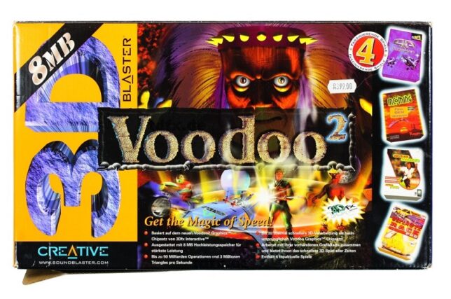
In the late ninetees, as a teenager I had the priveledge of owning a second hand Creative Labs 3dfx Voodoo 2 graphics card. It was an upgrade for my own hand-built PC – an AMD K6-2 333mhz system I had painstakingly saved up for and cobbled together.

Nostalgia running high, I recently set about building up a ‘retro’ gaming PC. With roughly the same specification as my original K6-2 machine from the late ninetees, it also features an original 3dfx Voodoo 2 accelerator card.

Unreal Tournament playing on my retro PC with the 3dfx Voodoo 2

The Brief Story of 3dfx Interactive and the Voodoo

A group of colleagues originally working together at SGI decided to break out and create 3dfx Interactive in San Jose, California (1994). This was after an initial failed attempt at selling rather pricey IrisVision boards for PCs.

Their original plan was to create specialist hardware solutions for arcade games, but they changed direction to instead design PC add-on boards. The reason for their pivot came about as a result of a few favourable factors. Namely:

  • The cost of RAM was low enough to make this a feasible endeavour.
  • RAM latency was much improved and allowed for ‘high’ clock speeds of up to 50MHz.
  • 3D games were picking up in popularity. Spearheaded initially no doubt by id software with games such as Wolfenstein 3D, DOOM, the market was clearly headed to a point where 3D accelerated graphics would be in demand.

The first design, the SST1 (marketed as the Voodoo 1), targeted the $300-$400 price range for consumer PCs. A variety of OEMs picked up the design and released their own reference design boards, leading to the success of the original Voodoo line-up of 3D accelerator cards.

Enter the Voodoo 2

After the initial success of the Voodoo 1, the 3dfx Voodoo 2 (SST2) was soon born. It had vastly improved specifications over the original SST1 design such as:

  • 100MHz clock rated EDO RAM (running at 90 MHz, 25 ns)
  • 90MHz ASICs
  • 2 x Texture Mapping Units (TMUs)

The fillrate of the Voodoo 2 was around 90 MPixels/s, and frame rates in benchmarks showed a massive uplift, nearly doubling in some cases.

My first (original) 3DFX Voodoo 2 PC Build

My first self-built (from scratch) PC was a bit of a frankenstein build. I had carefully budgeted and selected a motherboard that had onboard everything. Graphics, sound and networking. It would also run an AMD K6-2 CPU – a budget friendly option compared to Intel at that time.

The onboard graphics card shared 8MB of memory from system RAM (of which I only had 32MB total). As far as I recall it was capable of running Direct3D enabled games, albeit hobbling along with crippled frame rates.

Upgrading to a 3dfx Accelerator Card

After enduring this ‘fps hardship’ and learning more about the recently successful 3dfx graphics cards (a friend had a 4MB 3dfx Voodoo ‘1’ card), I found out about a second hand option. It was available through a friend of a friend, and would cost me 500.00 South African Rand (ZAR). This was a lot for a teen back then. I had saved up money, and bargained with my parents to combine my funds with a birthday gift contribution in order to purchase this card.

The Creative Labs 3D Blaster Voodoo 2. Mine came in almost identical packaging, but I had the 12MB version.

As I recall, I had to make massive concessions in order to fit the graphics card into my machine.

My motherboard only had 2 PCI slots. Both were horizontally in line with the CPU socket. The board design was probably never intended to house cards longer than the average PCI device at the time.

I had to remove the K6-2’s heatsink I was using and replace it with one from an older 486 machine that I had lying around. The profile of the 486 heatsink was much lower, allowing the 3dfx Voodoo 2 card to slot into a PCI slot, extending over the heatsink.

The problem now was that the 3dfx card’s lower PCB edge was now just about in direct contact with the heatsink. Another issue was that the heatsink was not made for mounting to a Socket 7 board. This forced me to lay my computer’s chassis down on it’s side in order for gravity to keep the heatsink in place!

I had a plan to keep pressure on the heatsink to maintain better contact with the CPU. Using a bit of non-conductive material between the 3dfx card’s PCB and the heatsink, I kept things in place. I also had to permanently angle a large fan blowing into the now open case.

This was the price I would pay to have my budget 3dfx voodoo 2 enabled system.

The Retro 3dfx Voodoo 2 PC Build

Recently after a bout of nostalgia and watching LGR videos, I started trawling eBay for old PC parts. The goal was to almost identically match my original PC build.

After a number of weeks of searching, I found the following parts. The motherboard was the most difficult to find (at a good price). Most Super Socket 7 boards I would find were dead and listed as spare parts.

all the parts for the Retro PC build, including the 3dfx voodoo 2 card.
Most of the parts lined up and ready for the build.
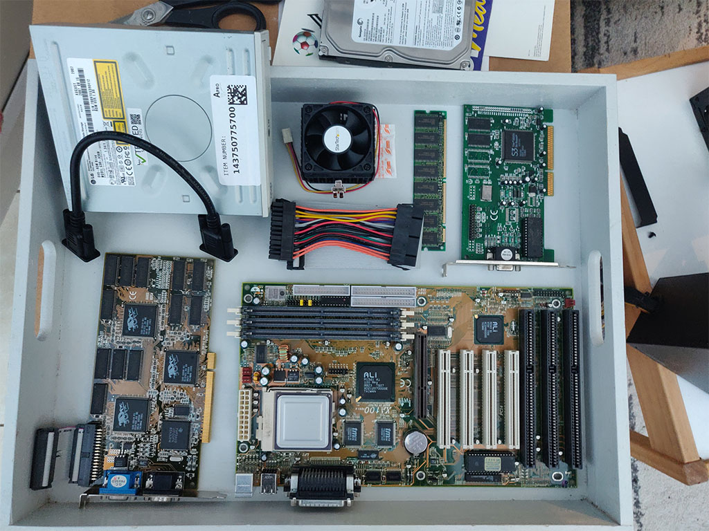
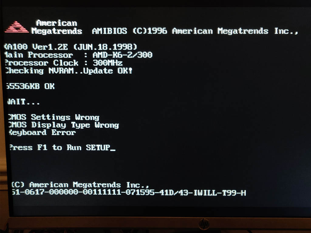
  • Iwill XA100 Aladdin V Super7 Motherboard, an AMD K6-2 300 CPU, and 64MB of PC100 SDRAM (168 pin)
  • S3 Trio 3D/2X graphics card (the Voodoo only handled 3D, and uses a loopback cable to plug into a ‘2D’ card)
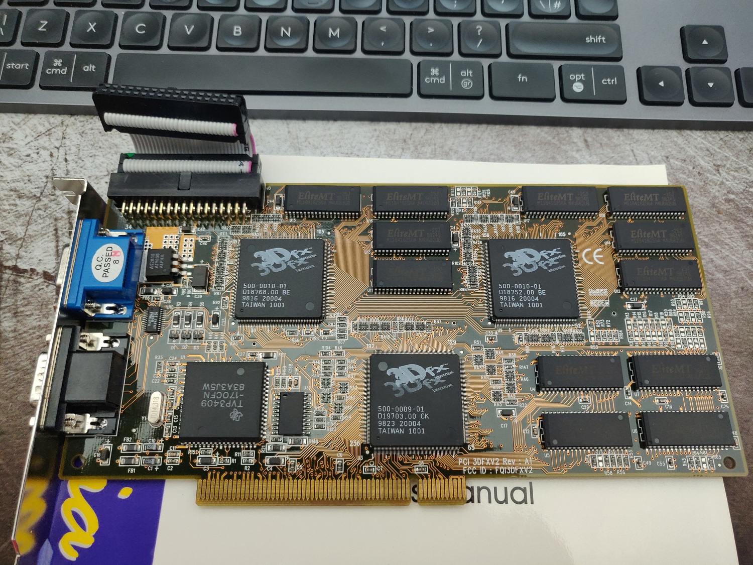
  • 3DFX JoyMedia Apollo 3D fast II 12Mb Video Card PCI Voodoo2 3DFX V2 Rev A1
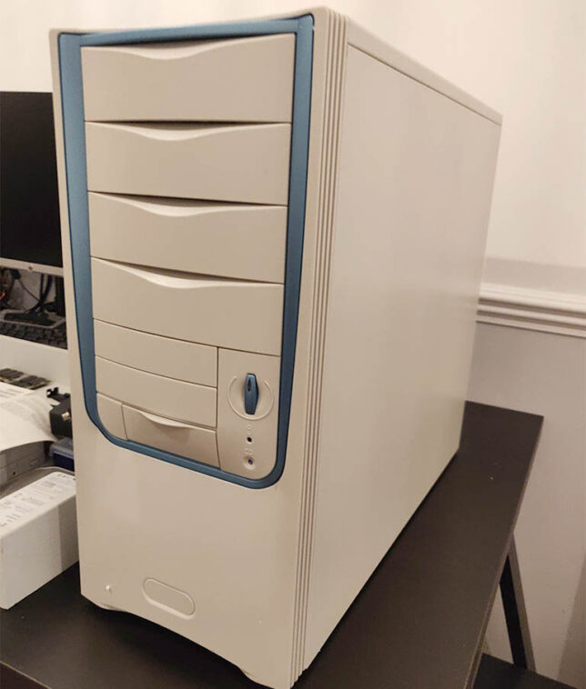
  • A Retro styled, beige ATX PC Chassis, Computer MIDI Tower Case
  • Creative Sound Blaster Live 5.1 Digital SB0220 PCI Sound Card
  • An 80GB IDE HDD, IDE ribbon cable, and an older DVD-R drive.
  • I used a modern 80 plus certified ATX power supply. It has a power connector with an older 20 pin layout which was perfect to re-use.

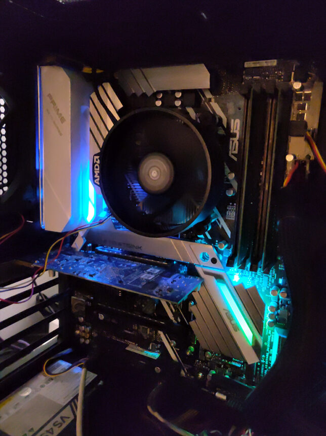
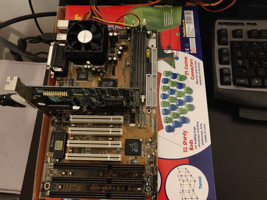
To test the hardware, I powered up the basic components on top of a cardboard box. Generally a good idea and especially so when using older hardware.

first bench test of the hardware.
‘Bench’ test of the hardware
POST checking the motherboard and components.
First POST successful, aside from USB keyboard not working (needed legacy option for USB enabled)
The ‘retro’ looking MIDI tower chassis I got for the build

Gaming on the Retro PC Build

After digging out a CD burner and an old image of Windows 98 SE, I’ve got an operating system running and have installed drivers along with a bunch of games.

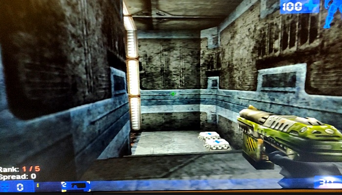
They play just as I remember. I’ve installed Quake, Quake 2, Unreal Tournament, and a few others to keep me busy for now.

unreal tournament game running with a 3dfx voodoo 2 accelerator card.
Unreal Tournament in Glide 3dfx rendered mode.

The next step is to replace the temporary modern day LCD monitor I’m using right now. A period correct CRT monitor would really complete the build. I remember Samsung SyncMaster CRTs being excellent. My aim is pick one of these up to complete the system.

If you’re nostalgic like me and want to revisit the PC and games hardware of the late 1990s I highly recommend a build like this.

Follow my ‘Retro’ PC series blog posts:

SpotiPod – Spotify Streaming Device from an iPod Classic

spotipod classic

I recently came across the sPot: Spotify in a 4th-gen iPod (2004) project on hackaday.io by Guy Dupont. This post is my go at building Guy’s project from the ground up – the SpotiPod.

Here is my version, up and running, albeit with some hardware leaking out the side for now…

The main components required in terms of hardware are:

  • iPod Classic (4th gen) – at least the device case and clickwheel components
  • A Raspberry Pi Zero W
  • 2″ LCD display (see note further on about an alternative)
  • 3.7V 1000mah LiPo battery
  • Adafruit boost module (to boost 3.7V to 5V required by the Pi, LCD, etc…
  • Adafruit USB charge controller module

Once it’s all connected and configured, you’ll be able to load up your own Spotify playlists and libraries, browse them, and play them all from your iPod Classic device over a bluetooth speaker or remote system.

The SpotiPod build almost complete.
Some wire reduction still required before I can completely close it up.

SpotiPod High-level Build

I won’t be getting into the low-level parts of the build, so for specific details I would recommend viewing Guy’s project log and branching off the posts there.

Initial Raspberry Pi Zero W setup with 2″ LCD display

I started off loading Raspbian Lite OS onto an 8GB microSD card and booting up a barebones Pi Zero W. The W version is important because it has WiFi and Bluetooth on the board.

My first task was to configure SSH to start automatically on boot. Useful when I have no display to start with. I also added some of the required software components to begin testing and messing around with, including redis server, compiling the click c++ application that Guy wrote to interface with the iPod’s clickwheel, and setting up some of the X11 components for a basic UI.

Soldering up the connection for the 2″ LCD display was my first hardware connection task. My soldering iron might come out once in a year, so I’m a bit of a novice in this area, but I managed the task on my first go.

Connecting the LCD to Raspberry Pi Zero via Composite Connector
testing the LCD
First LCD test successful

I posted more details here on the 2″ LCD connection and configuration in software.

Connecting the Charge Controller and Voltage Boost Modules

Next up I focused on getting the power delivery working. The goal was to be able to charge the LiPo battery via USB and have the circuit supply 5V to all SpotiPod components where required.

I familiarised myself with the Adafruit module documentation and pinout diagrams before connecting the circuit up.

  • Adafruit Powerboost 1000 module
  • Adafruit Charge Controller

Here is a useful diagram to follow, posted by Kakoub on the hackaday.io project page, re-hosted here in case the imgur upload ever disappears:

Click for a larger, clearer version

So after getting power delivery and connections soldered in place, and precariously placing all the components away from eachother to prevent shorts, here is where I was at:

SpotiPod Powerboost and Charge modules connected
Powerboost and Charge modules connected

Testing the Click wheel and Software

The click wheel connectivity is made easier with an 8 Pin FPC cable breakout board. I hooked this up next, soldering the 4 wires required for power and data.

The click wheel ribbon connector could then snap into the breakout board ribbon connector. This is by far the most delicate part of the build in my opinion. The ribbon cable is super thin and delicate.

Connecting the 8 pin FPC breakout board. My soldering skills slowly coming back with a bit of practice…

Testing the interface was a case of compiling the clickwheel program with gcc over an SSH connection then executing it with everything connected.

If wired up correctly, the program will output touch and click data to stdout.

iPod Classic click wheel testing over SSH

Gutting the old iPod Classic

I managed to snag an old iPod Classic 4th gen off eBay for about £20. It wasn’t working, but had the two bits I needed – the chassis, and the clickwheel.

Breaking out my trusty iFixit essentials toolkit, I set about opening it up to remove the unecessary components.

The method I found to work was to pry it open on the left and right edges using the pry tool. Once you can get into one of the edges, slide the tool around, and things get easier.

Insulating the case and components

With most of the electronics connected, I began insulating things with polyimide tape. Most importantly, the metal iPod case. I put down about three layers of tape and tried to cover all parts as best I could.

Insulating the iPod classic shell for the SpotiPod build.

Installing into the iPod Classic Case

This is the tricky part. It’s quite difficult to squeeze all the SpotiPod hardware in.

I started out by strengthening all my soldering connections with a bit of hot glue.

adding hot glue to the soldered connections for the SpotiPod
Adding hot glue to the soldered connections

After a bit of arranging, squeezing, and coercing, everything fits… Mostly!

Things are still not perfect though. I need to reduce my wire lengths before I can get the case to fully close.

For now though, everything works and I have a fully functional SpotiPod!

Tips and Tricks

I’ve put together a list of things that might help if you do this yourself. These are bits that I recall getting snagged on:

  • Make sure you setup all the X11 and software dependencies correctly. Getting Openbox and the frontend application to launch on start up can be tricky and this is crucial. Pay attention to your /etc/X11/xinit/xinitrc and /etc/xdg/openbox/autostart configurations.
  • You don’t have to use the more expensive Adafruit composite LCD display. Ricardo’s build at RSFlightronics uses a much cheaper LCD and some creative approaches to get display output working.
  • Watch out for the click wheel ribbon orientation when you connect it to the breakout board!
  • Use thin and short length wires for connections where possible. Not too short though as it is useful to be able to open the device up and put the two halves side-by-side.
  • Make sure you have a Spotify Premium subscription. I can’t remember exactly, but I’m sure that creating your own app to get your client and secret keys, or some of the scopes required for the app will only work on Premium. (It might have even been spotify connect).
  • You’ll need to configure your own Spotify App using the Spotify Developer portal. Keep your client and secret keys safe to yourself. Remember to setup environment variables with these that the openbox session can access.
  • The frontend/UI application has a hardcoded reference to the Spotify Connect device as “Spotifypod”. Keep things simple by setting your raspotify configuation to use this name too, otherwise you need to update the code too.
  • If you’re struggling to get the software side working at first, it can really help to setup VNC while you debug things. This allows you to get a desktop environment on the Pi Zero and execute scripts or programs in an x session as openbox would.

Thanks again to Guy Dupont for his excellent SpotiPod project and idea. Putting this all together really makes for a fun and rewarding hardware/software hacking experience.

Jarvis standing desk and workspace configuration

Jarvis standing desk setup

I recently invested in a standing desk for my home office. On the recommendation of a friend, I purchased the Jarvis Laminate Standing Desk from fully.com.

I’ve been working predominantly from home for around 1.5 years now (at least 4 days a week), and since going fully remote at 5 days a week after COVID-19 I decided to invest more in the home office.

After having noticed myself slouching at my desk on more than one occasion, I got curious about standing desks. After reading about the apparent benefits of standing more (as opposed to sitting at a desk all day), and on the recommendation of a friend I pulled the trigger on this fully motorised setup.

Here are the specifications and complete configuration I went for:

  • Jarvis Laminate Standing Desk (160 x 80 cm, black finish)
  • Jarvis Lifting Column, Mid Range
  • Jarvis Frame EU, Wide, Long Foot Programmable
  • WireTamer Cable Trays (2x)
  • Topo Mini Anti-fatigue mat

The total for the desk parts and standing mat came up to around £600 excluding VAT, which I think is a great price considering the health benefits it should bring about over the longer term.

The build

I got stuck in one evening after work, and thought it might be 2 hour job. I was very wrong. Here is photo I took of the chaos I unleashed in the office after taking down my old desk and beginning assembly of the Jarvis.

jarvis desk assembly, defeat.
Note the crossed legs, socks, and beer as I take a breather, almost admitting defeat for the night.

Soon I was making progress though.

jarvis standing desk progress
jarvis desk assembled and upright

Multi-monitor configuration

I’ve got two computers that needed setting up. One is my PC, the other is an Apple Mac Mini (the main work machine). So next on the list was a decent adjustable multi-monitor stand. I ended up getting:

  • FLEXIMOUNTS F6D Dual monitor mount LCD arm

This was the strongest arm I could find. I could not (at the time) find anything that would fit my 34″ Acer Predator ultra wide LCD. (It’s pretty heavy).

Although this mount is only compatible up to 30″ LCDs, it seems to cope with my Acer Predator on one side, and my LG 5K Retina 27″ LCD display on the other.

the monitor dual mount setup on the desk

Around midnight that evening I finally had everything configured and in order. I booted up both machines and raised the desk to try it out.

Adjusting to, and actually working at the desk

I’m not fully committed to standing all day (at least not yet). I tend to spend around 3 hours standing each day, and the remainder sitting. I’m slowly increasing the standing time as I go on.

The Top Mini anti-fatigue mat definitely helps. I also noticed wearing my light, minimalist running shoes feels good while standing and working too.

topo mini anti-fatigue mat
The topo mini mat

Some more angles of the full setup

Lastly, here are some photos of the final setup. Certainly a farcry and total overhaul since the days of this home office setup of mine circa 2009!

In summary, I’m very happy with the new setup. My office is a little narrow and crammed, but this configuration helps me move around a lot more and I feel better for it.

This is post #8 in my effort towards 100DaysToOffload.

Multipurpose FreeNAS Server Build

multipurpose freenas server build

There is something magical about building your own infrastructure from scratch. And when I say scratch, I mean using bare metal. This is a run through of my multipurpose FreeNAS server build process.

After scratching the itch recently with my Raspberry Pi Kubernetes Cluster, I got a hankering to do it again, and this build was soon in the works.

Part of my motivation came from my desire to reduce our reliance on cloud technology at home. Don’t get me wrong, I am an advocate for using the cloud where it makes sense. My day job revolves around designing and managing various clients’ cloud infrastructure.

At home, this was more about taking control of our own data.

I’ll skip to the juicy specifications part if you would like to know what hardware I used right away.

The intial hardware
Note: I got this Gigabyte B450 motherboard, but soon found out it did not support ECC.

Final specifications:

These are the final specifications I decided on. Scroll down to see the details about each area.

The Goals

The final home server build would need to meet many requirements:

  • It should provide a resilient, large shared storage pool for network file storage across multiple Windows PCs at home.
  • Support NFS storage for sharing persistent volumes to my Raspberry Pi Kubernetes Cluster.
  • It should be able to run Plex for home and remote media streaming.
  • It must be able to run Nextcloud for home and remote mobile file storage.
  • Run services in Virtual Machines, Jails, or Docker containers. For example, I like to run Pi-hole as a DNS server for all my home equipment and devices.

The Decision Process

I started out my search looking at two products. Unraid and FreeNAS.

I have had experience running FreeNAS in the past for home lab setups. I never really used it seriously with the goal of making it reliable though.

This time around, all my files would be at stake, so I did a fair bit of research into the features and offerings of both products.

Unraid performed quite well for me. But, what pushed me away from it was the fact that it is a paid for, closed source, commercial product.

Unraid does make it super easy to bundle storage together and expand that storage in future if need be. However FreeNAS’ use of ZFS and it’s various other features were what won me over.

The Build Details

Having settled on FreeNAS, I went about researching which hardware I would need. My goal here was to not spend too much money, but at the same time not cheap out and compromise on reliability.

CPU, Motherboard, RAM

ECC (Error Checking and Correction) RAM is very important for ZFS, so this is basically what my build hinged on.

I found that AMD Ryzen CPUs support ECC, and so do most Ryzen compatible motherboards.

Importantly, in my research I found that Ryzen APU CPUs do not support ECC. Make sure you do not get an APU if ECC is important to you.

Additionally, many others report much better stability running FreeNAS on AMD Ryzen Generation 2 chips and above. With this in mind, I decided I would use at least an AMD Ryzen 2xxx CPU.

On the ECC topic, I only found evidence of single bit error correction working on AMD Ryzen systems.

I also made an initial mistake here in my build buying a Gigabyte B450M DS3H motherboard. The product specs seem to indicate that it supports ECC, and so did a review I found on Anandtech. In reality the Gigabyte board does not support the ECC feature. Rather it ‘supports’ ECC memory by allowing the system to boot with ECC RAM installed, but you don’t get the actual error checking and correction!

I figured this out after booting it up with Fedora Rawhide as well as a couple of uBuntu Server distributions and running the edac-utils package. In all cases edac-utils failed to find ECC support / or any memory controller.

checking ECC support with edac-utils
Checking ECC support with edac-utils

The Asus board I settled on supports ECC and edac-utils confirmed this.

The motherboard also has an excellent EFI BIOS. I found it easy to get to the ECC and Virtualization settings.

the Asus Prime X470-Pro EFI BIOS

Storage

I used 4 x Western Digital 3TB Red hard drives for the RAIDZ1 main storage pool.

Western Digital 3TB Red hard drives

The SSD storage pool consists of 2 x Crucial MX500 250GB SSD SATA drives in a mirror configuration. This configuration is for running Virtual Machines and the NFS storage for my Kubernetes cluster.

Graphics Card

The crossing out of APUs also meant I would need a discrete graphic card for console / direct access, and to install the OS initially. I settled on a cheap PCI Express Graphics card off Ebay for this.

A cheap AMD Radeon HD 6450 1GB DVI DisplayPort PCI-Express Graphics Card I used for the FreeNAS build.

Having chosen a beefy six core Ryzen 2600 CPU, I decided I didn’t need to get a fancy graphics card for live media encoding. (Plex does much better with this). If media encoding speed and efficiency is important to you, then consider something like an nVIDIA or AMD card.

For me, the six core CPU does a fine job at encoding media for home and remote streaming over Plex.

Network

I wanted to use this system to server file storage for my home PCs and equipment. Besides this, I also wanted to export and share storage to my Raspberry Pi Kubernetes cluster, which runs on it’s own, dedicated network.

The simple solution for me here was multihoming the server onto the two networks. So I would need two network interface cards, with at least 1Gbit/s capability.

The motherboard already has an Intel NIC onboard, so I added two more ports with an Intel Pro Dual Port Gigabit PCI Express x4 card.

Intel dual port NIC

Configuration Highlights

I’ll detail the highlights of my configuration for each service the multipurpose FreeNAS Server build hosts.

Main System Setup

The boot device is the 120GB M.2 nVME SSD. I installed FreeNAS 11.3 using a bootable USB drive.

FreeNAS Configuration

I created two Storage Pools. Both are encrypted. Besides the obvious protection encryption provides, this also makes it easier to recycle drives later on if I need to.

FreeNAS storage pool configuration
  • Storage Pool 1
    • 4 x Western Digital Red 3TB drives, configured with RAIDZ1. (1 disk’s worth of storage is effectively lost for parity, giving roughly 8-9 TB of usable space).
    • Deduplication turned off
    • Compression enabled
  • Storage Pool 2
    • 2 x Crucial MX500 250GB SSD drives, configured in a Mirror (1 disk mirrors the other, providing a backup if one fails).
    • Deduplication turned off
    • Compression enabled

The network is set to use the onboard NIC to connect to my main home LAN. One of the ports on the Intel dual port NIC connects to my Raspberry Pi Kubernetes Cluster network and assigned a static IP address on that network.

Windows Shares

My home network’s storage shares are simple Windows SMB Shares.

I created a dedicated user in FreeNAS which I configured in the SMB share configuration ACLs to give access.

Windows machines then simply mount the network location / path as mapped drives.

I also enabled Shadow Copies. FreeNAS supports this to enable Windows to use Shadow Copies.

FreeNAS Windows SMB share

Pi-hole Configuration

I setup a dedicated uBuntu Server 18.04 LTS Virtual Machine using FreeNAS’ built-in VM support (bhyve). Before doing this, I enabled virtualization support in the motherboard BIOS settings. (SVM Mode = Enabled).

I used the standard installation method for Pi-Hole. I made sure the VM was using a static IP address and was bridged to my home network. Then I reconfigured my home DHCP server to dish out the Pi-hole’s IP address as the primary DNS server to all clients.

For the DNS upstream servers that Pi-hole uses, I chose to use the Quad9 (filtered, DNSSEC) ones, and enabled DNSSEC.

pi-hole upstream DNS configuration with DNSSEC

NextCloud

NextCloud has a readily available plugin for FreeNAS. However, out of the box you get no SSL. You’ll need to setup your networking at home to allow remote access. Additionally, you’ll need to get an SSL certificate. I used Let’s Encrypt.

I detailed my full process in this blog post.

Plex

Plex was a simple setup. Simply install the Plex FreeNAS plugin from the main Plugins page and follow the wizard. It will install and configure a jail to run Plex.

To mount your media, you need to stop the Plex jail and edit it to add your media location on your storage. Here is an example of my mount point. It basically mounts the media directory I use to keep all my media into the Plex Jail’s filesystem.

Plex jail mount point

NFS Storage for Kubernetes

Lastly, I setup an NFS share / export for my Raspberry Pi Kubernetes Cluster to use for Persistent Volumes to attach to pods.

NFS shares for Kubernetes in FreeNAS

The key points here were that I allowed the two network ranges I wanted to have access to this storage from. (10.0.0.0/8 is my Kubernetes cluster network). I also configured a Mapall user of ‘root’, which allows the storage to be writeable when mounted by pods/containers in Kubernetes. (Or any other clients that mount this storage).

I was happy with this level of access for this particular NFS storage share from these two networks.

Next, I installed the NFS External-storage provisioner for Kubernetes on my Pi Cluster. I needed to use the ARM specific deployment manifest as Pi’s of course have ARM CPUs.

I modified the deployment manifest to point it to my FreeNAS machine’s IP address and NFS share path.

The kubernetes nfs client provisioner manifest configured for NFS storage provisioning.

With that done, pods can now request persistent storage with a Persistent Volume Claim (PVC). The NFS client provisioner will create a directory for the pod (named after the pod itself) on the NFS mount and mount that to your pod.

Final Thoughts

So far the multipurpose FreeNAS server build has been very stable. It has been happily serving our home media streaming, storage, and shared storage needs.

It’s also providing persistent storage for my Kubernetes lab environment which is great, as I prefer not to use the not-so-durable microSD cards on the Raspberry Pi’s themselves for storage.

The disk configuration size seems fine for our needs. At the moment we’re only using ~20% of the total storage, so there is plenty of room to grow.

I’m also happy with the ability to run custom VMs or Jails for additional services, though I might need to add another 16GB of ECC RAM in the future to support more as ZFS does well with plenty of memory.

Three PowerCLI scripts for information gathering – VMs, Hosts, etc


I was on a vSphere upgrade review engagement recently, and part of this involved checking hardware and existing vSphere VI was compatible with the targeted upgrade.

To help myself along, I created a few PowerCLI scripts to help with information gathering to CSV for the VI parts – such as Host Versions, build numbers, VMware tools and hardware versions, etc… These scripts were built to run once-off, simply either by copy/pasting them into your PowerCLI console, or by running them from the PowerCLI console directly.

They can easily be adapted to collect other information relating to VMs or hosts. To run, just launch PowerCLI, connect to the VC in question (using Connect-VIServer) and then copy/paste these into the console. The output will be saved to CSV in the directory you were in. Just make sure you unblock the zip file once downloaded if you execute them directly from PowerCLI, otherwise the copy/paste option mentioned above will work fine too.

There are three scripts bundled in the zip file:

  • Gather all hosts under the connected vCenter server and output Host name, Model and Bios version results to PowerCLI window and CSV
  • Gather all hosts under the connected vCenter server and output Host name, Version and Build version results to PowerCLI window and CSV
  • Gather all hosts under the specified DC and output VM name and hardware version results to PowerCLI window and CSV

Short and simple scripts, but hopefully they will come in handy to some. As mentioned above, these can easily be extended to fetch other information about items in your environment. Just take a look at the way existing info is fetched, and adapt from there. Also remember that using | gm (get-member) on objects in PowerShell is your friend – you can discover all the properties and methods on PowerShell objects by using this, and use those to enhance your reports/outputs in your scripts.

[wpdm_package id=’2025′]