I was pointed to Helm the other day and decided to have a quick look at it. I tasked myself with setting it up in a sandbox environment and deploying a pre-packaged application (a.k.a chart, or helm package) into my Kubernetes sandbox environment.
Helm 101
The best way to think about Helm is as a ‘package manager for Kubernetes’. You install Helm as a cli tool (It’s written in Golang) and all the operations it provides to you, you’ll find are very similar to those of common package managers like npm etc…
Helm has a few main concepts.
- As mentioned above, a ‘Chart’ is a package for Helm. It contains the resource definitions required to run an app/tool/service on a Kubernetes cluster.
- A ‘Repository’ is where charts are stored and shared from
- A ‘Release’ is an instance of a chart running in your Kubernetes cluster. You can create multiple releases for multiple instances of your app/tool/service.
More info about Helm and it’s concepts can be found on the Helm Quickstart guide. If however, you wish to get stuck right in, read on…
This is a quick run-down of the tasks involved in setting it up and deploying a chart (I tried out kube-slack to provide slack notifications for failed kubernetes operations in my sandbox environment to my slack channel).
Setting up Helm
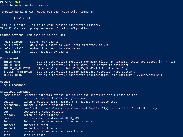
Download and unzip the latest Helm binary for your OS. I’m using Windows so I grabbed that binary, unblocked it, and put in a folder found in my path. Running a PowerShell session I can simply type:
helm
Helm executes and provides a list of possible options.
Before you continue with initialising Helm, you should create a service account in your cluster that Helm will use to manage releases across namespaces (or in a particular namespace you wish it to operate in). For testing its easiest to set up the service account to use the default built-in “cluster-admin” role. (To be more secure you should set up Tiller to have restricted permissions and even restrict it based on namespace too).
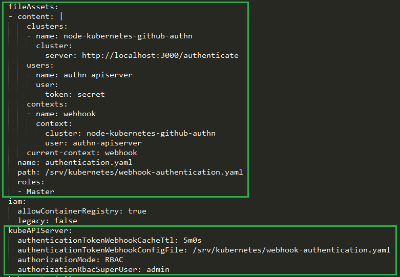
To setup the basic SA with the cluster-admin role, you’ll need a ClusterRoleBinding to go with the SA. Here is the config you need to set both up.
apiVersion: v1
kind: ServiceAccount
metadata:
  name: tillersa
  namespace: kube-system
---
apiVersion: rbac.authorization.k8s.io/v1beta1
kind: ClusterRoleBinding
metadata:
  name: tillersa-clusterrolebinding
roleRef:
  apiGroup: rbac.authorization.k8s.io
  kind: ClusterRole
  name: cluster-admin
subjects:
  - kind: ServiceAccount
    name: tillersa
    namespace: kube-system
Run kubectl create and point to this config to set up the SA and ClusterRoleBinding:
kubectl create -f .\tillersa-and-cluster-rolebinding.yaml
![]()
Now you can do a helm initialisation.
helm init --service-account tillersa --tiller-namespace kube-system
If all went well, you’ll get a message stating it was initialised and setup in your cluster.
Run:
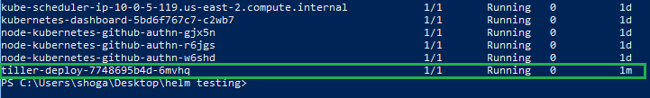
kubectl get pods -n=kube-system
and you should see your new tiller-deploy pod running.
Deploying Charts with Helm
Run helm list to see that you currently have no chart releases deployed.
helm list
You can search the public Helm repository for charts (applications/tools/etc) that you can now easily deploy into your cluster.
helm search
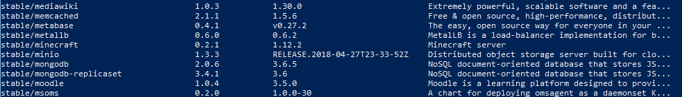
Search for ‘grafana’ with helm. We’ll deploy that to the cluster in this example.
helm search grafana

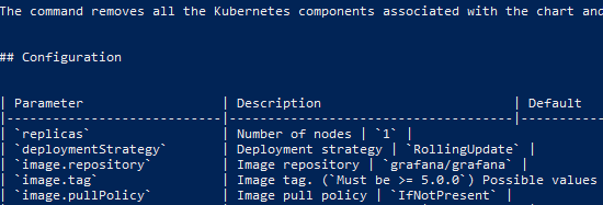
Next up you might want to inspect and discover more about the chart you’re going to install. This is useful to see what sort of configuration parameters you can pass to it to customise it to your requirements.
helm inspect grafana
Choose a namespace in your cluster to deploy to and a service type for Grafana (to customise it slightly to your liking) and then run the following, replacing the service.type and service.port values for your own. For example you could use a ClusterIP service instead of LoadBalancer like I did:
helm install --name sean-grafana-release stable/grafana --set service.type=LoadBalancer --set service.port=8088 --namespace sean-dev
Helm will report back on the deployment it started for your release.
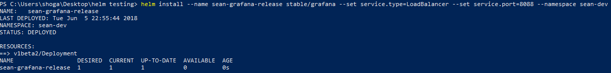
The command is not synchronous so you can run helm status to report on the status of a release.
helm status sean-grafana-release
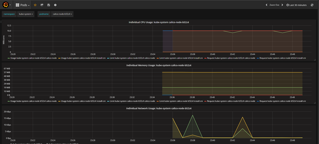
Check on deployments in your namespace with kubectl or the Kubernetes dashboard and you should find Grafana running happily along.
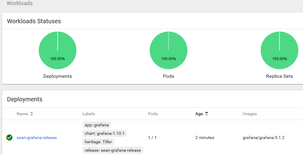
In my case I used a LoadBalancer service, so my cluster being AWS based spun up an ELB to front Grafana. Checking the ELB endpoint on port 8088 as I specified in my Helm install command sure enough shows my new Grafana app’s login page.

The chart ensures all the necessary components are setup and created in your cluster to run Grafana. Things like the deployment, the service, service account, secrets, etc..
In this case the chart outputs instructions on how to retrieve your Grafana admin password for login. You can see how to get that in the output of your release.
Tidy Up
To clean up and delete your release simply do:
helm delete sean-grafana-release
Concluding
Done!
There is plenty more to explore with helm. If you wish to change your helm configuration with helm init, look into using the –upgrade parameter. helm reset can be used to remove Helm from your cluster and there are many many more options and scenarios that could be covered.
Explore further with the helm command to see available commands and do some digging.
Next up for me I’ll be looking at converting one of my personal applications into a chart that I can deploy into Kubernetes.