I recently came across a scenario requiring CloudWatch log ingestion to a private Splunk HEC (HTTP Event Collector).
The first and preferred method of ingesting CloudWatch Logs into Splunk is by using AWS Firehose. The problem here though is that Firehose only seems to support an endpoint that is open to the public.
This is a problem if you have a Splunk HEC that is only available inside of a VPC and there is no option to proxy public connections back to it.
The next thing I looked at was the Splunk AWS Lambda function template to ingest CloudWatch logs from Log Group events. I had a quick look and it seems pretty out of date, with synchronous functions and libraries in use.
So, I decided to put together a small AWS Lambda Serverless project to improve on what is currently out there.
async / await, and for promised that wrap the synchronous libraries like zlib.
A module that handles identification of Log Group names based on a custom regex pattern. If events come from log groups that don’t match the naming convention, then they get rejected. The idea is that you can write another small function that auto-subscribes Log Groups.
Secrets Manager integration for loading the Splunk HEC token from Secrets Manager. (Or fall back to a simple environment variable if you like).
Serverless framework wrapper. Pass in your Security Group ID, Subnet IDs and tags, and let serverless CLI deploy the function for you.
Lambda VPC support by default. You should deploy this Lambda function in a VPC. You could change that, but my idea here is that most enterprises would be running their own internal Splunk inside of their corporate / VPC network. Change it by removing the VPC section in serverless.yml if you do happen to have a public facing Splunk.
You deploy it using Serverless framework, passing in your VPC details and a few other options for customisation.
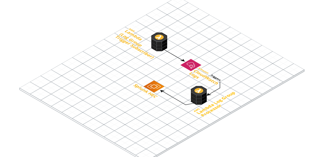
Once configured, it’ll pick up any log events coming in from Log Groups you’ve ‘subscribed’ it to (Lambda CloudWatch Logs Triggers).
These events get enriched with extra metadata defined in the function. The metadata is derived by default from the naming convention used in the CloudWatch Log Groups. Take a close look at the included Regex pattern to ensure you name your Log Groups appropriately. Finally, they’re sent to your Splunk HEC for ingestion.
For an automated Log Group ingestion story, write another small helper function that:
Looks for Log Groups that are not yet subscribed as CloudWatch Logs Triggers.
Adds them to your CloudWatch to Splunk HEC function as a trigger and enables it.
In the future I might add this ‘automatic trigger adding function’ to the Github repository, so stay tuned!
Splitting a tmux session window into multiple panes can do wonders for productivity. Here you’ll see how easy synchronizing tmux panes is.
But, what if you would like to use this feature to automate a workflow across many machines?
You’ll be glad to know it is possible to synchronize panes in a tmux window. This allows you to execute a series of commands or particular workflow across many machines.
First of all, if you haven’t already, split your window into the panes you need. The commands for this of course (assuming CTRL + B is prefix for tmux commands) are:
You may wish at this point to connect each pane to the relevant machine you want in each.
Synchronize the panes by entering tmux command mode with:
CTRL + B, :
Now type:
setw synchronize-panes on
Hit enter and you’ll immediately notice all the panes are now synchronized. At this point you can go wild and execute whichever workflow you want to automate across the subjects.
You can toggle the synchronization off again by entering command mode once more and typing:
:setw synchronize-panes off
You can also use the same command to toggle synchronization on/off by omitting the on/off parameter on the end. Synchronizing tmux Panes is toggled when omitting this parameter.
There is something magical about building your own infrastructure from scratch. And when I say scratch, I mean using bare metal. This is a run through of my multipurpose FreeNAS server build process.
After scratching the itch recently with my Raspberry Pi Kubernetes Cluster, I got a hankering to do it again, and this build was soon in the works.
Part of my motivation came from my desire to reduce our reliance on cloud technology at home. Don’t get me wrong, I am an advocate for using the cloud where it makes sense. My day job revolves around designing and managing various clients’ cloud infrastructure.
At home, this was more about taking control of our own data.
I’ll skip to the juicy specifications part if you would like to know what hardware I used right away.
Note: I got this Gigabyte B450 motherboard, but soon found out it did not support ECC.
Final specifications:
These are the final specifications I decided on. Scroll down to see the details about each area.
It should be able to run Plex for home and remote media streaming.
It must be able to run Nextcloud for home and remote mobile file storage.
Run services in Virtual Machines, Jails, or Docker containers. For example, I like to run Pi-hole as a DNS server for all my home equipment and devices.
The Decision Process
I started out my search looking at two products. Unraid and FreeNAS.
I have had experience running FreeNAS in the past for home lab setups. I never really used it seriously with the goal of making it reliable though.
This time around, all my files would be at stake, so I did a fair bit of research into the features and offerings of both products.
Unraid performed quite well for me. But, what pushed me away from it was the fact that it is a paid for, closed source, commercial product.
Unraid does make it super easy to bundle storage together and expand that storage in future if need be. However FreeNAS’ use of ZFS and it’s various other features were what won me over.
The Build Details
Having settled on FreeNAS, I went about researching which hardware I would need. My goal here was to not spend too much money, but at the same time not cheap out and compromise on reliability.
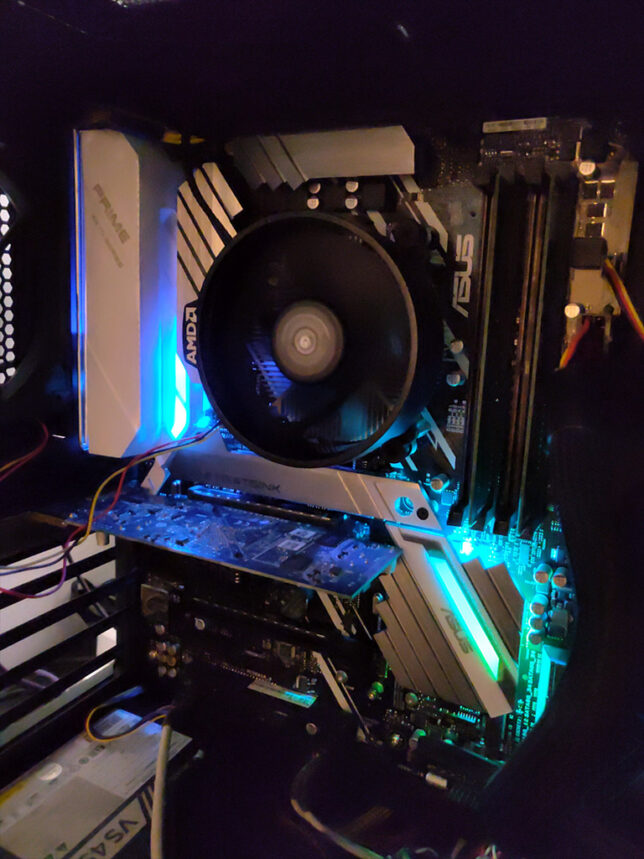
CPU, Motherboard, RAM
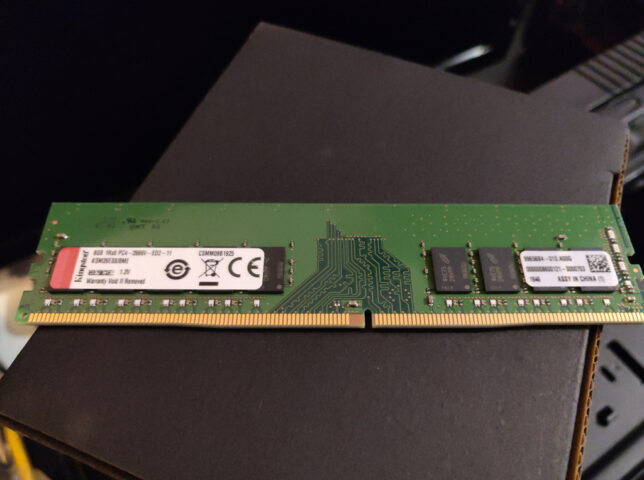
ECC (Error Checking and Correction) RAM is very important for ZFS, so this is basically what my build hinged on.
I found that AMD Ryzen CPUs support ECC, and so do most Ryzen compatible motherboards.
Importantly, in my research I found that Ryzen APU CPUs do not support ECC. Make sure you do not get an APU if ECC is important to you.
Additionally, many others report much better stability running FreeNAS on AMD Ryzen Generation 2 chips and above. With this in mind, I decided I would use at least an AMD Ryzen 2xxx CPU.
I also made an initial mistake here in my build buying a Gigabyte B450M DS3H motherboard. The product specs seem to indicate that it supports ECC, and so did a review I found on Anandtech. In reality the Gigabyte board does not support the ECC feature. Rather it ‘supports’ ECC memory by allowing the system to boot with ECC RAM installed, but you don’t get the actual error checking and correction!
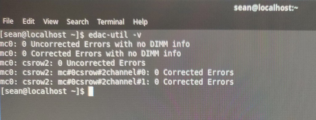
I figured this out after booting it up with Fedora Rawhide as well as a couple of uBuntu Server distributions and running the edac-utils package. In all cases edac-utils failed to find ECC support / or any memory controller.
Checking ECC support with edac-utils
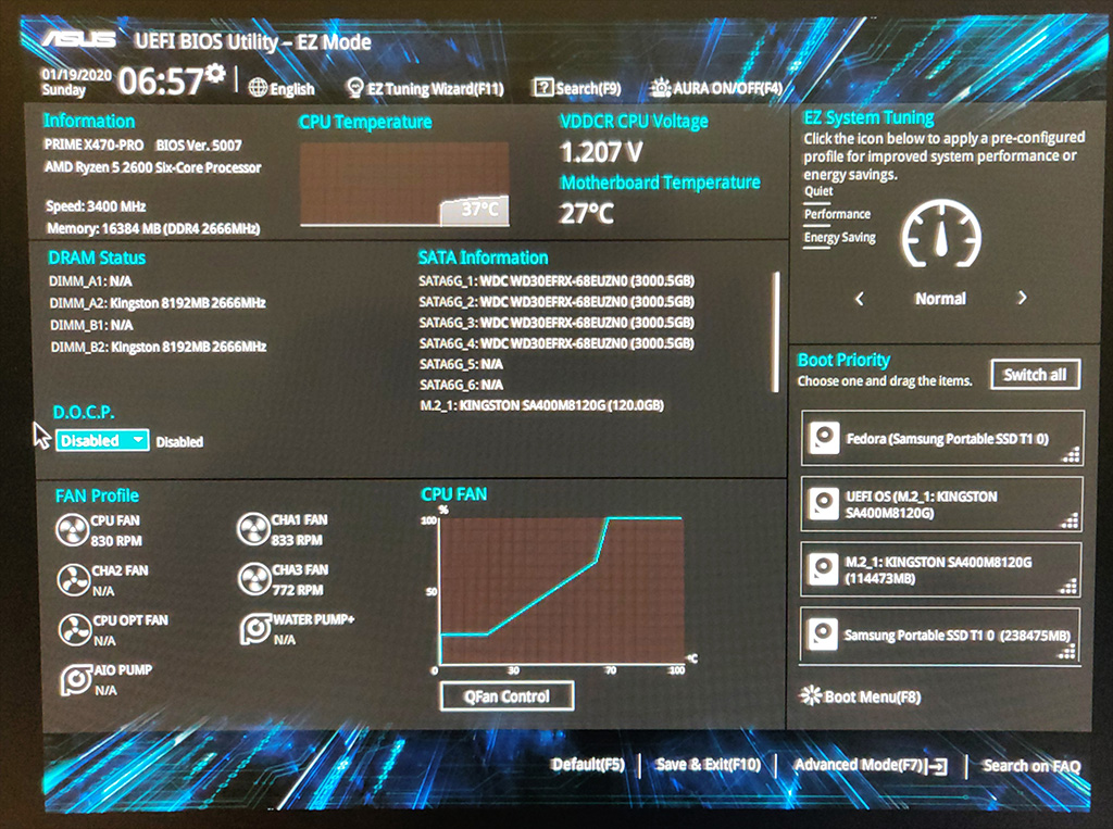
The Asus board I settled on supports ECC and edac-utils confirmed this.
The motherboard also has an excellent EFI BIOS. I found it easy to get to the ECC and Virtualization settings.
Storage
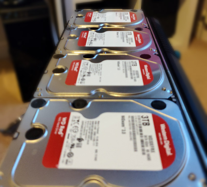
I used 4 x Western Digital 3TB Red hard drives for the RAIDZ1 main storage pool.
The SSD storage pool consists of 2 x Crucial MX500 250GB SSD SATA drives in a mirror configuration. This configuration is for running Virtual Machines and the NFS storage for my Kubernetes cluster.
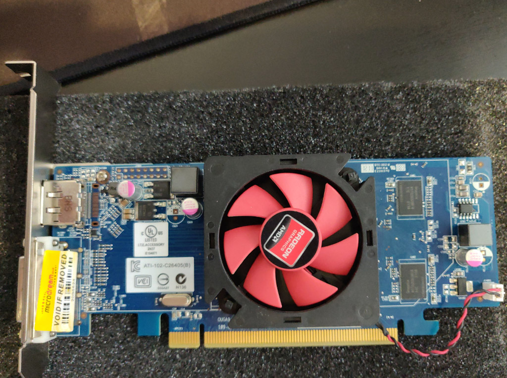
Graphics Card
The crossing out of APUs also meant I would need a discrete graphic card for console / direct access, and to install the OS initially. I settled on a cheap PCI Express Graphics card off Ebay for this.
Having chosen a beefy six core Ryzen 2600 CPU, I decided I didn’t need to get a fancy graphics card for live media encoding. (Plex does much better with this). If media encoding speed and efficiency is important to you, then consider something like an nVIDIA or AMD card.
For me, the six core CPU does a fine job at encoding media for home and remote streaming over Plex.
Network
I wanted to use this system to server file storage for my home PCs and equipment. Besides this, I also wanted to export and share storage to my Raspberry Pi Kubernetes cluster, which runs on it’s own, dedicated network.
The simple solution for me here was multihoming the server onto the two networks. So I would need two network interface cards, with at least 1Gbit/s capability.
The motherboard already has an Intel NIC onboard, so I added two more ports with an Intel Pro Dual Port Gigabit PCI Express x4 card.
Configuration Highlights
I’ll detail the highlights of my configuration for each service the multipurpose FreeNAS Server build hosts.
Main System Setup
The boot device is the 120GB M.2 nVME SSD. I installed FreeNAS 11.3 using a bootable USB drive.
FreeNAS Configuration
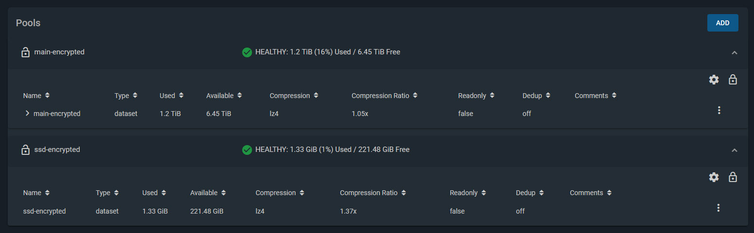
I created two Storage Pools. Both are encrypted. Besides the obvious protection encryption provides, this also makes it easier to recycle drives later on if I need to.
Storage Pool 1
4 x Western Digital Red 3TB drives, configured with RAIDZ1. (1 disk’s worth of storage is effectively lost for parity, giving roughly 8-9 TB of usable space).
Deduplication turned off
Compression enabled
Storage Pool 2
2 x Crucial MX500 250GB SSD drives, configured in a Mirror (1 disk mirrors the other, providing a backup if one fails).
Deduplication turned off
Compression enabled
The network is set to use the onboard NIC to connect to my main home LAN. One of the ports on the Intel dual port NIC connects to my Raspberry Pi Kubernetes Cluster network and assigned a static IP address on that network.
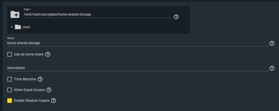
Windows Shares
My home network’s storage shares are simple Windows SMB Shares.
I created a dedicated user in FreeNAS which I configured in the SMB share configuration ACLs to give access.
Windows machines then simply mount the network location / path as mapped drives.
I also enabled Shadow Copies. FreeNAS supports this to enable Windows to use Shadow Copies.
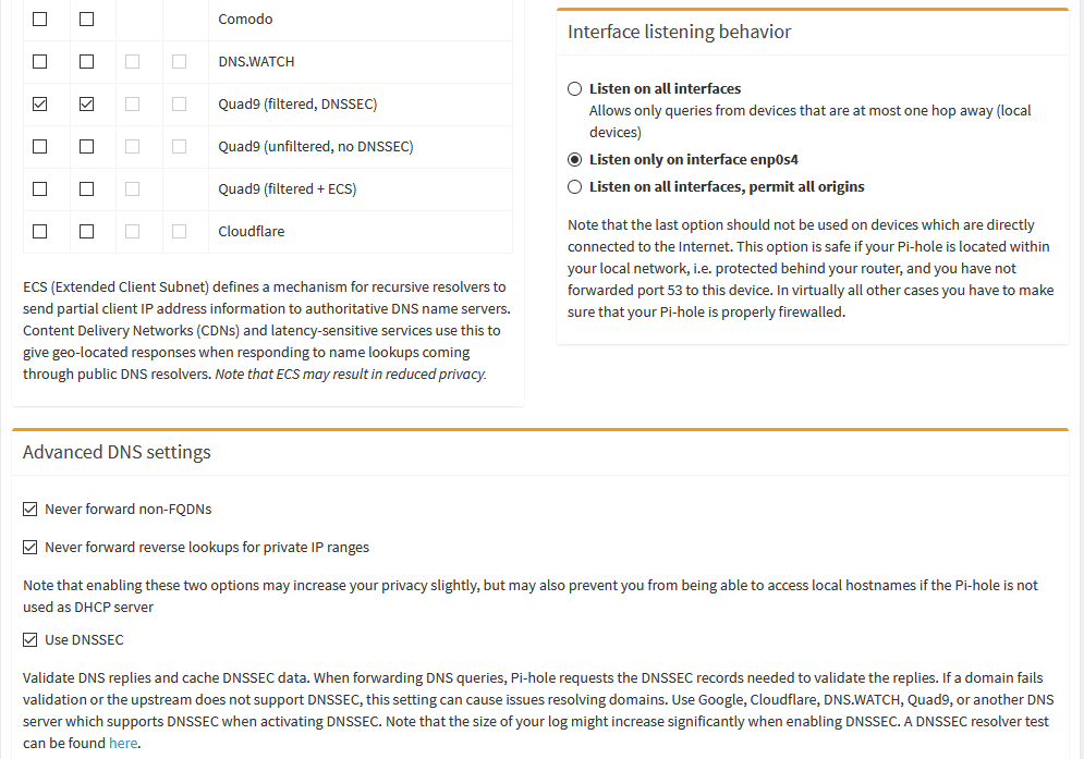
Pi-hole Configuration
I setup a dedicated uBuntu Server 18.04 LTS Virtual Machine using FreeNAS’ built-in VM support (bhyve). Before doing this, I enabled virtualization support in the motherboard BIOS settings. (SVM Mode = Enabled).
I used the standard installation method for Pi-Hole. I made sure the VM was using a static IP address and was bridged to my home network. Then I reconfigured my home DHCP server to dish out the Pi-hole’s IP address as the primary DNS server to all clients.
For the DNS upstream servers that Pi-hole uses, I chose to use the Quad9 (filtered, DNSSEC) ones, and enabled DNSSEC.
NextCloud
NextCloud has a readily available plugin for FreeNAS. However, out of the box you get no SSL. You’ll need to setup your networking at home to allow remote access. Additionally, you’ll need to get an SSL certificate. I used Let’s Encrypt.
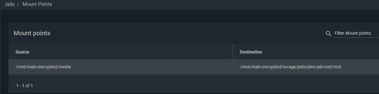
Plex was a simple setup. Simply install the Plex FreeNAS plugin from the main Plugins page and follow the wizard. It will install and configure a jail to run Plex.
To mount your media, you need to stop the Plex jail and edit it to add your media location on your storage. Here is an example of my mount point. It basically mounts the media directory I use to keep all my media into the Plex Jail’s filesystem.
NFS Storage for Kubernetes
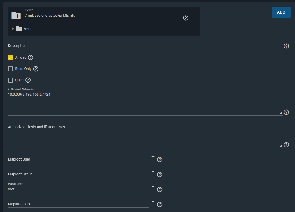
Lastly, I setup an NFS share / export for my Raspberry Pi Kubernetes Cluster to use for Persistent Volumes to attach to pods.
The key points here were that I allowed the two network ranges I wanted to have access to this storage from. (10.0.0.0/8 is my Kubernetes cluster network). I also configured a Mapall user of ‘root’, which allows the storage to be writeable when mounted by pods/containers in Kubernetes. (Or any other clients that mount this storage).
I was happy with this level of access for this particular NFS storage share from these two networks.
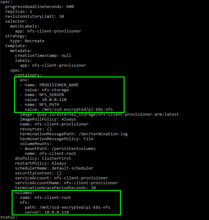
I modified the deployment manifest to point it to my FreeNAS machine’s IP address and NFS share path.
With that done, pods can now request persistent storage with a Persistent Volume Claim (PVC). The NFS client provisioner will create a directory for the pod (named after the pod itself) on the NFS mount and mount that to your pod.
Final Thoughts
So far the multipurpose FreeNAS server build has been very stable. It has been happily serving our home media streaming, storage, and shared storage needs.
It’s also providing persistent storage for my Kubernetes lab environment which is great, as I prefer not to use the not-so-durable microSD cards on the Raspberry Pi’s themselves for storage.
The disk configuration size seems fine for our needs. At the moment we’re only using ~20% of the total storage, so there is plenty of room to grow.
I’m also happy with the ability to run custom VMs or Jails for additional services, though I might need to add another 16GB of ECC RAM in the future to support more as ZFS does well with plenty of memory.
The FreeNAS Nextcloud plugin installation works great with automatic configuration thanks to a recent pull request. But, you don’t get SSL enabled by default. This is critical, especially for a system exposed to the internet.
In this post you’ll see how to:
Install the Nextcloud plugin in a FreeNAS BSD jail
Add an extra NAT port for SSL to the jail
Configure NGINX inside the jail by adding a customised configuration with SSL enabled
Apply a free SSL certificate using Lets Encrypt and DNS-01 challenge validation
Look at some options for setting up home networking for public access
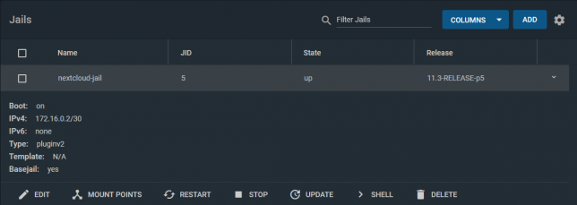
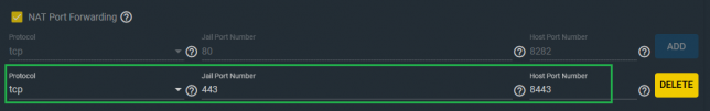
Start off by Installing the Nextcloud Plugin in a jail. Choose NAT for networking mode. It defaults to port 8282:80 (http).
Stop the jail once it’s running and edit it. Add another NAT rule to point 8443 to 443 for SSL.
The reason for selecting port 8443 for Nextcloud is because the FreeNAS web UI listens on port 443 for SSL too.
An alternative could be to use DHCP instead of NAT for the jail. I chose NAT for my setup as I prefer using one internal IP address for everything I run on the FreeNAS server.
Shell into the Nextcloud jail, and rename the default nginx configuration.
NGINX will load all .conf files in this directory. Hence the reason you’ll create a new configuration for your SSL setup here.
ee /usr/local/etc/nginx/conf.d/nextcloud-ssl.conf
Populate it with the contents of the gist below, but replace server_name, ssl_certificate, and ssl_certificate_key with your own hostname.
Generate a free SSL certificate with Lets Encrypt
To configure the Nextcloud plugin on FreeNAS with SSL you don’t need to break the bank on SSL certificate costs from traditional CAs. Lets Encrypt it free, but you’ll need to renew your certificate every three months.
DNS-01 challenge certificate generation for Lets Encrypt is a great way to get SSL certificates without a public web server.
It entails creating a TXT/SPF record on the domain you own, with a value set to a code that certbot gives you during the certbot request process.
Install certbot if you don’t already have it installed. On a debian based system:
sudo apt-get install certbot
Request a certificate for your desired hostname using certbot with dns as the preferred challenge.
sudo certbot -d yournextcloud.example.net --manual --preferred-challenges dns certonly
Follow the prompts until you receive a code to setup your own TXT record with. Go to your DNS provider control panel and create it with the code you’re given as the value.
After creating the record, finish the certificate request. Lets Encrypt will confirm the DNS TXT record and issue you a certificate. You’ll get a chain file called fullchain.pem, along with a private key file called privkey.pem.
Upload the SSL certificate files to Nextcloud
Upload both to your Nextcloud Jail. Use SCP to copy them up, renaming them as follows:
Rename them as per your chosen hostname to keep things organised, and so that they match your nextcloud-ssl.conf file entries.
Port forwarding / NAT setup
This is the part that comes down to your own network setup. I use a double NAT setup, so I NAT traffic from my external router interface, through to another internal router.
From my internal router, I port forward / NAT from the internal router interface through to my FreeNAS box on port 8443.
From there, the Nextcloud jail does NAT to take the TCP traffic from 8443 to 443 inside the jail (where NGINX is listening on 443).
This is how my NAT and port forwarding chain looks:
Public_IP:29123 (WAN interface) -> Internal_IP:29123 (Internal router LAN interface) -> Internal_IP:8443 (FreeNAS LAN interface) -> Internal_IP:443 (Nextcloud Jail)
If you’re lucky enough to have a static IP address then you can point your DNS host record to your static IP. Otherwise you’ll neee to use some form of dynamic DNS service.
At this point you should have everything in place.
Final steps
Using a shell in the Nextcloud jail, restart nginx with service nginx restart. If all goes well you’ll see nginx started in the output of that command.
If not, you’re likely to have an NGINX configuration syntax error.
The logs are usually good about pinpointing these, so read them to see where you might have missed something obvious in the nextcloud-ssl.conf file. Adjust any errors and restart again.
The default credentials that for Nextcloud are in the home directory of the jail (/root). To retrieve them:
cat /root/ncuser
cat /root/ncpassword
Test logging in, and get started with personalising your Nextcloud system and adding some users.
Now you can enjoy the Nextcloud plugin on FreeNAS with SSL enabled.
This is the third post in this series and the focus will be on completing the Raspberry Pi Kubernetes cluster by adding a worker node. You’ll also setup a software based load-balancer implementation designed for bare metal Kubernetes Clusters by leveraging MetalLB.
Here are some handy links to other parts in this blog post series:
By now you should have 1 x Pi running as the dedicated Pi network router, DHCP, DNS and jumpbox, as well as 1 x Pi running as the cluster Master Node.
Of course it’s always best to have more than 1 x Master node, but as this is just an experimental/fun setup, one is just fine. The same applies to the Worker nodes, although in my case I added two workers with each Pi 4 having 4GB RAM.
Joining a Worker Node to the Cluster
Start off by completing the setup steps as per the Common Setup section in Part 2 with your new Pi.
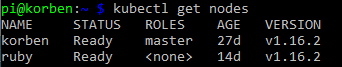
Once your new Worker Pi is ready and on the network with it’s own static DHCP lease, join it to the cluster (currently only the Master Node) by using the kubeadm join command you noted down when you first initialised your cluster in Part 2.
After a few moments, SSH back to your master node and run kubectl get nodes. You should see the new worker node added and after it pulls down and starts the weave net CNI image it’s status will change to Ready.
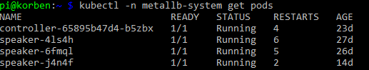
Setting up MetalLB
The problem with a ‘bare metal’ Kubernetes cluster (or any self-installed, manually configured k8s cluster for that matter) is that it doesn’t have any load-balancer implementation to handle LoadBalancer service types.
When you run Kubernetes on top of a cloud hosting platform like AWS or Azure, they are backed natively by load-balancer implementations that work seamlessly with those cloud platform’s load-balancer services. E.g. classic application or elastic load balancers with AWS.
However, with a Raspberry Pi cluster, you don’t have anything fancy like that to provide LoadBalancer services for your applications you run.
MetalLB provides a software based implementation that can work on a Pi cluster.
Install version 0.8.3 of MetalLB by applying the following manifest with kubectl:
Update the addresses section to use whichever range of IP addresses you would like to assign for use with MetalLB. Note, I only used 10 addresses as below for mine.
Apply the configuration:
kubectl apply -f ./metallb-config.yaml
Setup Helm in the Pi Cluster
First of all you’ll need an ARM compatible version of Helm. Download it and move it to a directory that is in your system PATH. I’m using my Kubernetes master node as a convenient location to use kubectl and helm commands from, so I did this on my master node.
Note: it uses a custom image from jessestuart/tiller (as this is ARM compatible). The command also replaces the older api spec for the deployment with the apps/v1 version, as the older beta one is no longer applicable with Kubernetes 1.16.
Deploy an Ingress Controller with Helm
Now that you have something to fulfill LoadBalancer service types (MetalLB), and you have Helm configured, you can deploy an NGINX Ingress Controller with a LoadBalancer service type for your Pi cluster.
If you list out your new ingress controller pods though you might find a problem with them running. They’ll likely be trying to use x86 architecture images instead of ARM. I manually patched my NGINX Ingress Controller deployment to point it at an ARM compatible docker image.
kubectl set image deployment/nginx-ingress-controller nginx-ingress-controller=quay.io/kubernetes-ingress-controller/nginx-ingress-controller-arm:0.26.1
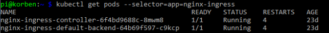
After a few moments the new pods should now show as running:
Now to test everything, you can grab the external IP that should have been assigned to your NGINX ingress controller LoadBalancer service and test the default NGINX backend HTTP endpoint that returns a simple 404 message.
List the service and get the EXTERNAL-IP (this should sit in the range you configured MetalLB with):
kubectl get service --selector=app=nginx-ingress
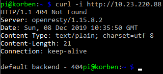
Curl the NGINX Ingress Controller LoadBalancer service endpoint with a simple GET request:
curl -i http://10.23.220.88
You’ll see the default 404 not found response which indicates that the controller did indeed receive your request from the LoadBalancer service and directed it appropriately down to the default backend pod.
Concluding
At this point you’ve configured:
A Raspberry Pi Kubernetes network Router / DHCP / DNS server / jumpbox
Kubernetes master node running the master components for the cluster
Kubernetes worker nodes
MetalLB load-balancer implementation for your cluster
Helm client and Tiller agent for ARM in your cluster
NGINX ingress controller
In part 1, recall you setup some iptables rules on the Router Pi as an optional step?
These PREROUTING AND POSTROUTING rules were to forward packets destined for the Router Pi’s external IP address to be forwarded to a specific IP address in the Kubernetes network. In actual fact, the example I provided was what I used to forward traffic from the Pi router all the way to my NGINX Ingress Controller load balancer service.
Revisit this section if you’d like to achieve something similar (access services inside your cluster from outside the network), and replace the 10.23.220.88 IP address in the example I provided with the IP address of your own ingress controller service backed by MetalLB in your cluster.
Also remember that at this point you can add as many worker nodes to the cluster as you like using the kubeadm join command used earlier.